
random user submitted photo
The VeeCU
The VeeCU
Hi Guys,
Retirement is supposed to be the time you do all those things you always wanted to do but just didn't have the time while you were working. I've been retired for over three years now and I'm chipping away at the list. I wanted to build a Onex from the day it was introduced, check. The wife and I always wanted to get a travel trailer and visit the state parks, in work. And, I always wanted to work an engineering project outside the corporate environment, just for the sheer fun of it.
Well, it's time to start on #3. The project will be an Engine Control Unit for my Onex. I am serious about the product but now that I have no title, no company, and no reputation to uphold, I can poke fun at myself. While I'm at it I'll poke some fun at corporate America and all of characters that play a part.
Enter the first character, Bud. Bud's a BD (Business Development) guy. Ref. ("https://www.urbandictionary.com/define.php?term=BD%20guy"). Bud is responsible for the title of this thread. He caught wind of what I was doing and immediately called a brain storming session to name the product.
The second character is Harold. I met Harold right out of school. Harold is the prototypical insecure engineer. He obsesses over every single detail. He wears dark rim glasses and the right ear piece is held on with adhesive tape. Harold comes complete with pocket protector and lives in constant fear of making a mistake. One more thing, Harold's personal hygiene is somewhat lacking. Harold is a hardware guy. Last time I saw Harold he was walking in circles muttering something about load dumps, slew rates, electromagnetic radiation, and input signal conditioning. I'll leave him alone for now. He'll calm down eventually.
I'll play a small part myself. I enjoy the software more than hardware. Like Harold I'm a bit of a social invalid. And..., I don't have a very good filter between my brain and my mouth. That's caused me grief my entire life, especially with the Suits.
Oh yes, the Suits. The Suits are an exceedingly odd group of folks, not like the rest of us. A Suit is likely to have their very own bathroom. I'm not sure why they want to live with their flatulence but it seems to be a status symbol. One things for sure, Suits have no sense of humor. You have to be very careful with these guys, they hold the purse strings. If a Suit ever approaches you with an "idea they've had", even if it is a hopelessly and obviously flawed idea, don't say a word. If you have to say something just say "Wow". Freeze, stare off into space as if awe struck by a truly original thought. After a few moments ask for some time to think about it. Now, you need to train for this situation, just like pushing the nose over on a loss of power, the response needs to be automatic. If you're lucky that will be the end of it. If not there are multiple full back positions. For those I charge a consulting fee.
Project details to follow.
Wes
Wes Ragle
Onex #89
Conventional Gear
Long Tips
Hummel 2400 w/Zenith Carb
Prince P Tip 54x50
First Flight 06/23/2020
42.8 Hrs. as of 10/30/21
Onex #89
Conventional Gear
Long Tips
Hummel 2400 w/Zenith Carb
Prince P Tip 54x50
First Flight 06/23/2020
42.8 Hrs. as of 10/30/21
- WesRagle
- Posts: 899
- Joined: Fri Jan 05, 2018 12:35 pm
- Location: Weatherford, Tx
Re: The VeeCU
Just a reminder, I know this is not an economically viable project. This is therapy for me. All in good fun.
All I have is a text editor, no word processing software, I probably need to fix that.
So, here is a first cut at a top level document. If you think the verbiage sounds a bit like marketing fluff you're right. Top level documents always start off that way. It's an attempt to capture the intent of a product. From an engineering standpoint the top level document provides a place to record some basic system characteristics that can later be fleshed out into full blown requirements. If anybody sees a problem with the content let me know and I'll fix it.
VeeCU Top Level Document Rev 0.01
Introduction:
The VeeCU is a microprocessor based Engine Control Unit designed specifically for air cooled Volkswagen engines that have been converted for aircraft use. The VeeCU is not designed to replace the engine's existing induction and ignition systems but rather it is designed to augments those systems. The VeeCU provides all of the the benefits of port fuel injection and electronic ignition while retaining the existing manual systems as a proven backup.
In addition to the benefits of a traditional port fuel injection system the VeeCU allows the installer to trim each injector individually eliminating the fuel imbalance common to many VW conversions. The electronic ignition works in conjunction with fuel injection and provides optimum spark advance for rock solid idle and maximum fuel economy while cruising lean of peak.
The VeeCU's compact size and rugged design allow it to be installed in the engine compartment thus minimizing wiring clutter in the cockpit.
Inputs:
Secondary Ignition Module Output (Front Cylinders)
Scaling 0 Hz = 0 RPM, 60 Hz = 3600 RPM
Range 0 - 5000 RPM
Secondary Ignition Module Output (Rear Cylinders)
Scaling 0 Hz = 0 RPM, 60 Hz = 3600 RPM
Range 0 - 5000 RPM
Primary Ignition (P-Lead)
Scaling 0 Hz = 0 RPM, 60 Hz = 3600 RPM
Range 0 - 5000 RPM
Manifold Air Pressure
Scaling TBD Volts = 20 Kpa, TBD Volts = 110 Kpa
Range 20 - 110 Kpa
Inlet Air Temperatre
Scaling TBD Volts = -40 Deg. C., TBD Volts = 70 Deg. C.
Range -40 - 70 Deg. C.
Mixture Control
Scaling TBD Angular Deg. CCW = -50 Pcnt., TBD Angular Deg. CW = +50 Pcnt.
Range -50 - +50 Pcnt
Communication Port
ARINC 825 data bus @ 1 Meg bit per second
Outputs:
Secondary Ignition Coil Input (Front Cylinders)
Secondary Ignition Coil Input (Rear Cylinders)
Four (4) High Impedance Injector drives.
Fuel Flow output. Open Collector output most likely simulating a Red Cube.
ARINC 825 data bus @ 1 Meg bit per second
Dimentions:
TBD
Weight:
TBD
Pinout:
TBD
Environmental:
In accordance with D0160X ...
Wes Ragle
Onex #89
Conventional Gear
Long Tips
Hummel 2400 w/Zenith Carb
Prince P Tip 54x50
First Flight 06/23/2020
42.8 Hrs. as of 10/30/21
Onex #89
Conventional Gear
Long Tips
Hummel 2400 w/Zenith Carb
Prince P Tip 54x50
First Flight 06/23/2020
42.8 Hrs. as of 10/30/21
- WesRagle
- Posts: 899
- Joined: Fri Jan 05, 2018 12:35 pm
- Location: Weatherford, Tx
Re: The VeeCU
Hi Guys,
Some progress on the ECU.
The CPU is up and running with a small Real Time Kernel.
The four pulsed input channels have been implemented using one of the 32 bit timers. The edge on which the timer capture happens is programmable, so right now I'm just using a spare timer to drive the inputs for both front and rear coil secondary inputs. One captures on the rising edge and the other on the falling edge. Frequency and pulse width measurement is made to one micro-Sec.
The internal AtoD is a 12 bit SAR type with with 18 possible inputs. By the time I allocated all the pins needed for coil drivers, injector drivers, etc., there were 11 pins left for use as analog inputs. Right now I am measuring 11 external pins and two internal signals, core CPU Temp, and internal reference voltage. The AtoD is running in batch acquisition mode with all channels sampled and summed 8 times, shifted right 2 bits (so as to leave a rounding bit) and then dumped to memory via a DMA channel. The DMA terminal count ISR sums the new readings to four groups of readings. Each secondary ignition capture generates an interrupt which grabs the group with the most samples, copies it to a working group, and then zeros that group. Anyway, that gives me an average of the AtoD readings over the last two revolutions of the engine. I may change strategy during testing, but that's the plan for now.
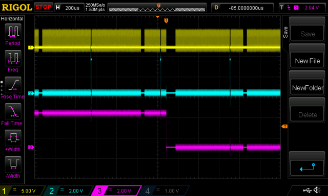
Two output bits have been allocated to verify/test timing.
The pics below shows timing bit #1, timing bit #2, and one edge of the "engine" timer. Timing bit #1 is toggled by the "idle" task. Any gap in toggling means either an ISR or a higher priority task is executing. In this pic Timing bit #2 is toggled at the beginning and end of the AtoD DMA terminal count ISR.
Looking at timing bit #1 you can see the AtoD DMA terminal count ISR, the Kernel timer tick ISR every mSec (along with the tasks triggered by the timer tick), and the input capture ISR (and the input capture task) generated by edge on trace #3. At present the input capture ISR just stores the captured value and signals the input capture task. In the future it will also output pulses for ignition and fuel injection. As you can see, the CPU is very lightly loaded at present.
The input capture task buffers the captured reading in a 30 reading circular buffer, calculates the period of the last revolution, the RPMS based on that period, and an RPM based on 0.3 second gate time (for display). This task also scales all of the AtoD readings to engineering units for use in calculating pulse width and phase for output.
I also bought the evaluation board for an ASIC (Application Specific Integrated Circuit) which targets 4 cylinder engine engine control. The ASIC provides a CAN bus driver, power for the CPU, two five volt outputs for sensor excitation, four injector drives, four pre-drives for the IGBTs that drive the ignition coils, and a lot of outputs that will go unused.

Up next is pulse generation followed by bringing up the Arinc 825 bus for communication with the control head.
Forever Forward,
Wes
Some progress on the ECU.
The CPU is up and running with a small Real Time Kernel.
The four pulsed input channels have been implemented using one of the 32 bit timers. The edge on which the timer capture happens is programmable, so right now I'm just using a spare timer to drive the inputs for both front and rear coil secondary inputs. One captures on the rising edge and the other on the falling edge. Frequency and pulse width measurement is made to one micro-Sec.
The internal AtoD is a 12 bit SAR type with with 18 possible inputs. By the time I allocated all the pins needed for coil drivers, injector drivers, etc., there were 11 pins left for use as analog inputs. Right now I am measuring 11 external pins and two internal signals, core CPU Temp, and internal reference voltage. The AtoD is running in batch acquisition mode with all channels sampled and summed 8 times, shifted right 2 bits (so as to leave a rounding bit) and then dumped to memory via a DMA channel. The DMA terminal count ISR sums the new readings to four groups of readings. Each secondary ignition capture generates an interrupt which grabs the group with the most samples, copies it to a working group, and then zeros that group. Anyway, that gives me an average of the AtoD readings over the last two revolutions of the engine. I may change strategy during testing, but that's the plan for now.
Two output bits have been allocated to verify/test timing.
The pics below shows timing bit #1, timing bit #2, and one edge of the "engine" timer. Timing bit #1 is toggled by the "idle" task. Any gap in toggling means either an ISR or a higher priority task is executing. In this pic Timing bit #2 is toggled at the beginning and end of the AtoD DMA terminal count ISR.
Looking at timing bit #1 you can see the AtoD DMA terminal count ISR, the Kernel timer tick ISR every mSec (along with the tasks triggered by the timer tick), and the input capture ISR (and the input capture task) generated by edge on trace #3. At present the input capture ISR just stores the captured value and signals the input capture task. In the future it will also output pulses for ignition and fuel injection. As you can see, the CPU is very lightly loaded at present.
The input capture task buffers the captured reading in a 30 reading circular buffer, calculates the period of the last revolution, the RPMS based on that period, and an RPM based on 0.3 second gate time (for display). This task also scales all of the AtoD readings to engineering units for use in calculating pulse width and phase for output.

I also bought the evaluation board for an ASIC (Application Specific Integrated Circuit) which targets 4 cylinder engine engine control. The ASIC provides a CAN bus driver, power for the CPU, two five volt outputs for sensor excitation, four injector drives, four pre-drives for the IGBTs that drive the ignition coils, and a lot of outputs that will go unused.

Up next is pulse generation followed by bringing up the Arinc 825 bus for communication with the control head.
Forever Forward,
Wes
Wes Ragle
Onex #89
Conventional Gear
Long Tips
Hummel 2400 w/Zenith Carb
Prince P Tip 54x50
First Flight 06/23/2020
42.8 Hrs. as of 10/30/21
Onex #89
Conventional Gear
Long Tips
Hummel 2400 w/Zenith Carb
Prince P Tip 54x50
First Flight 06/23/2020
42.8 Hrs. as of 10/30/21
- WesRagle
- Posts: 899
- Joined: Fri Jan 05, 2018 12:35 pm
- Location: Weatherford, Tx
Re: The VeeCU
HI Guys,
I've been working on ignition pulses today. I want to feel comfortable using the secondary ignition for ground operations so I want to minimize current draw at lower engine speeds. So... the focus today has been timing AND "dwell".
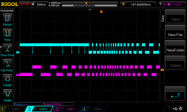
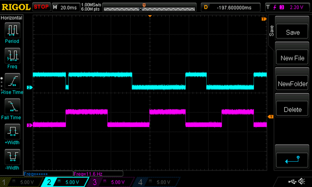
The following simulation sweeps the input from the secondary ignition module, the bottom trace (remember it will be adjusted to TDC) through a start sequence. The top trace is the wire that will be routed to the forward ignition coil and will trigger a spark on the falling edge of that signal. To test the control, below 500 RPM the spark is fired at TDC for 3 mSec. Above 500 RPM the dwell is adjusted to 25 mSec and advanced 90 Deg. (because it's easy to look at). Exact advance and dwell will be calculated later.
The sequence:
Zoom at the transition from Start to Run (500 RPM).
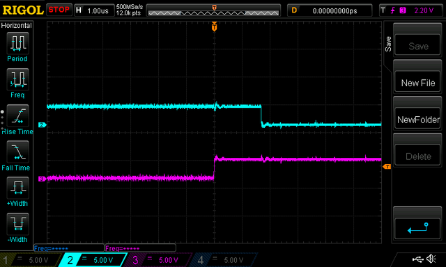
Latency from ignition module input (the highest priority interrupt in the system) to spark generation during TDC firing.
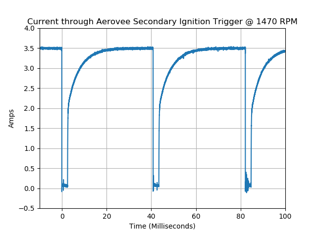
Based on the following pic provided by Chris Madsen, 25 ms of dwell (on time) should be more than adequate to charge the coil. At idle (900 RPM) that amounts to a duty cycle of 0.375 which should cut the current consumption of the secondary ignition by at least half at idle. Using 5 Ohm coils should bring the secondary ignition current down to between 2 and 2.5 amps total at idle.
Recent testing has shown that there is just over 1 micro second of jitter in interrupt latency due to short critical sections in the real time kernel. That amounts to 0.0216 angular degrees of uncertainty at 3600 RPM. Nothing to worry about.
Also, the CPU is so low power that the core temperature only increases 2 centigrade degrees over ambient while running.
Did I mention that my Wife bought a travel trailer? Off on another vacation.
Wes
I've been working on ignition pulses today. I want to feel comfortable using the secondary ignition for ground operations so I want to minimize current draw at lower engine speeds. So... the focus today has been timing AND "dwell".
The following simulation sweeps the input from the secondary ignition module, the bottom trace (remember it will be adjusted to TDC) through a start sequence. The top trace is the wire that will be routed to the forward ignition coil and will trigger a spark on the falling edge of that signal. To test the control, below 500 RPM the spark is fired at TDC for 3 mSec. Above 500 RPM the dwell is adjusted to 25 mSec and advanced 90 Deg. (because it's easy to look at). Exact advance and dwell will be calculated later.
The sequence:

Zoom at the transition from Start to Run (500 RPM).

Latency from ignition module input (the highest priority interrupt in the system) to spark generation during TDC firing.

Based on the following pic provided by Chris Madsen, 25 ms of dwell (on time) should be more than adequate to charge the coil. At idle (900 RPM) that amounts to a duty cycle of 0.375 which should cut the current consumption of the secondary ignition by at least half at idle. Using 5 Ohm coils should bring the secondary ignition current down to between 2 and 2.5 amps total at idle.

Recent testing has shown that there is just over 1 micro second of jitter in interrupt latency due to short critical sections in the real time kernel. That amounts to 0.0216 angular degrees of uncertainty at 3600 RPM. Nothing to worry about.
Also, the CPU is so low power that the core temperature only increases 2 centigrade degrees over ambient while running.
Did I mention that my Wife bought a travel trailer? Off on another vacation.
Wes
Wes Ragle
Onex #89
Conventional Gear
Long Tips
Hummel 2400 w/Zenith Carb
Prince P Tip 54x50
First Flight 06/23/2020
42.8 Hrs. as of 10/30/21
Onex #89
Conventional Gear
Long Tips
Hummel 2400 w/Zenith Carb
Prince P Tip 54x50
First Flight 06/23/2020
42.8 Hrs. as of 10/30/21
- WesRagle
- Posts: 899
- Joined: Fri Jan 05, 2018 12:35 pm
- Location: Weatherford, Tx
Re: The VeeCU
I'm kind of excited about your project and your postings. Of course, the only thing I understood in all of these posts was, "My wife bought a travel trailer".
Nevertheless, I would love to see this working, and in the fleet. Keep at it!
Nevertheless, I would love to see this working, and in the fleet. Keep at it!
Lou Pappas
Phoenix, AZ
RV-7A Flying (2024)
Waiex B Turbo (2016)
RV-8 (2009)
Waiex Legacy 3300 (2007)
Hiperlight SNS-9 (1991)
Falcon Ultralight (1989)
Phoenix, AZ
RV-7A Flying (2024)
Waiex B Turbo (2016)
RV-8 (2009)
Waiex Legacy 3300 (2007)
Hiperlight SNS-9 (1991)
Falcon Ultralight (1989)
- pappas
- Posts: 352
- Joined: Wed Feb 15, 2017 11:27 am
Re: The VeeCU
Hi Lou,
Thanks. I'll keep at it and see where it leads. After this upcoming trip I'll clean up the ignition code and add the injection pulses. That will probably be about a week of testing and study. Then I'll bring up the communication bus.
You probably noticed me talking about the "Real Time Kernel". The neat thing about having a kernel is that you can have multiple tasks (sub-programs) running on the same CPU with the highest priority program (that has something to do) running at any particular time. I mention this because the communication bus (CAN bus) can be initialized in "loop back" mode. In loop back mode the CAN transceiver receives what it transmits. In that mode I can insert a task that mimics the control head and perfect the communication protocol before I actually have to start wiring things together. The longer I can keep the project confined to a single CPU the faster I can make progress.
Anyway, it really is great fun and very inexpensive compared to building an airplane. The CPU board I'm using to breadboard the proof of concept cost a whopping $15.
My wife works jigsaw puzzles and I do this :-)
Wes
Wes Ragle
Onex #89
Conventional Gear
Long Tips
Hummel 2400 w/Zenith Carb
Prince P Tip 54x50
First Flight 06/23/2020
42.8 Hrs. as of 10/30/21
Onex #89
Conventional Gear
Long Tips
Hummel 2400 w/Zenith Carb
Prince P Tip 54x50
First Flight 06/23/2020
42.8 Hrs. as of 10/30/21
- WesRagle
- Posts: 899
- Joined: Fri Jan 05, 2018 12:35 pm
- Location: Weatherford, Tx
Re: The VeeCU
Maybe we should talk some more about the jigsaw puzzles. I’m on the same apparently sink8ng ship as Lou...
Cheers, Gordon
Cheers, Gordon
Waiex 158 New York. N88YX registered.
3.0 Liter Corvair built, run, and installed.
Garmin panel, Shorai LiFePo batteries.
3.0 Liter Corvair built, run, and installed.
Garmin panel, Shorai LiFePo batteries.
- GordonTurner
- Posts: 668
- Joined: Tue Feb 21, 2012 1:14 am
- Location: NY, NY
Re: The VeeCU
Hi Gordon,
The VeeCU will intercept the ignition pulses coming from the secondary ignition module and use those pulses, in lieu of a crank sensor, to time fuel injection and the actual ignition pulses delivered to the secondary ignition coils. The secondary ignition will be adjusted to TDC (0 Deg. advance). The longer I can keep the project on the desk top the faster software development goes. So, simulation is key to rapid software development.
Since the MPU (Micro processing unit) has 16 timers on board, I am using one of the spare timers to simulate the pulses coming from the secondary ignition module. In it's final form there will be input signal conditioning circuitry between the secondary ignition module and the MPU but I can ignore that for now.
Thinking about the end game, there will be two pulse streams coming from the secondary ignition module. One pulse per revolution on each stream with the pulses occurring 180 Deg. apart. Since the pulses are accepted on an edge and since the edge on which they are accepted is programmable, for the sake of simulation I can program the forward coil (from the secondary ignition module) to be accepted on a rising edge and the rear coil to be accepted on the falling edge. That way I can use the same square wave to drive both MPU secondary ignition inputs. Clear as mud?
Back to the previous image:

The bottom trace is the square wave simulating both pulses coming from the secondary ignition module with edges occurring at TDC. Looking at the top trace, those pulses will be driving the circuitry that actually fires the front ignition coil. While starting, that signal is driven low for 3 mSec right at TDC. The signal then goes back high to recharge the coil. Once the engine speed is up to 500 RPM ( 8.33 Hz) The ignition pulse is driven low 90 Deg. (1/4 of the signal period) before TDC. The signal is then driven high to recharge the coil ~25 mSec before it is fired again at 90 Deg. before TDC and so on.
Kinda hard to talk about but that's what's going on :-)
Wes
The VeeCU will intercept the ignition pulses coming from the secondary ignition module and use those pulses, in lieu of a crank sensor, to time fuel injection and the actual ignition pulses delivered to the secondary ignition coils. The secondary ignition will be adjusted to TDC (0 Deg. advance). The longer I can keep the project on the desk top the faster software development goes. So, simulation is key to rapid software development.
Since the MPU (Micro processing unit) has 16 timers on board, I am using one of the spare timers to simulate the pulses coming from the secondary ignition module. In it's final form there will be input signal conditioning circuitry between the secondary ignition module and the MPU but I can ignore that for now.
Thinking about the end game, there will be two pulse streams coming from the secondary ignition module. One pulse per revolution on each stream with the pulses occurring 180 Deg. apart. Since the pulses are accepted on an edge and since the edge on which they are accepted is programmable, for the sake of simulation I can program the forward coil (from the secondary ignition module) to be accepted on a rising edge and the rear coil to be accepted on the falling edge. That way I can use the same square wave to drive both MPU secondary ignition inputs. Clear as mud?
Back to the previous image:

The bottom trace is the square wave simulating both pulses coming from the secondary ignition module with edges occurring at TDC. Looking at the top trace, those pulses will be driving the circuitry that actually fires the front ignition coil. While starting, that signal is driven low for 3 mSec right at TDC. The signal then goes back high to recharge the coil. Once the engine speed is up to 500 RPM ( 8.33 Hz) The ignition pulse is driven low 90 Deg. (1/4 of the signal period) before TDC. The signal is then driven high to recharge the coil ~25 mSec before it is fired again at 90 Deg. before TDC and so on.
Kinda hard to talk about but that's what's going on :-)
Wes
Wes Ragle
Onex #89
Conventional Gear
Long Tips
Hummel 2400 w/Zenith Carb
Prince P Tip 54x50
First Flight 06/23/2020
42.8 Hrs. as of 10/30/21
Onex #89
Conventional Gear
Long Tips
Hummel 2400 w/Zenith Carb
Prince P Tip 54x50
First Flight 06/23/2020
42.8 Hrs. as of 10/30/21
- WesRagle
- Posts: 899
- Joined: Fri Jan 05, 2018 12:35 pm
- Location: Weatherford, Tx
Re: The VeeCU
I’ll continue to monitor and input my my keen guidance to help you keep the project on track.
:)
:)
Waiex 158 New York. N88YX registered.
3.0 Liter Corvair built, run, and installed.
Garmin panel, Shorai LiFePo batteries.
3.0 Liter Corvair built, run, and installed.
Garmin panel, Shorai LiFePo batteries.
- GordonTurner
- Posts: 668
- Joined: Tue Feb 21, 2012 1:14 am
- Location: NY, NY
Re: The VeeCU
OK, great, give me a poke when you get to the part about how the inverse relationship between interest rates and bond prices in the secondary market begins to have an effect on the ignition firing sequence, and I may have some helpful input!
Lou Pappas
Phoenix, AZ
RV-7A Flying (2024)
Waiex B Turbo (2016)
RV-8 (2009)
Waiex Legacy 3300 (2007)
Hiperlight SNS-9 (1991)
Falcon Ultralight (1989)
Phoenix, AZ
RV-7A Flying (2024)
Waiex B Turbo (2016)
RV-8 (2009)
Waiex Legacy 3300 (2007)
Hiperlight SNS-9 (1991)
Falcon Ultralight (1989)
- pappas
- Posts: 352
- Joined: Wed Feb 15, 2017 11:27 am
Who is online
Users browsing this forum: No registered users and 4 guests


