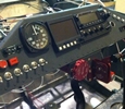


random user submitted photo
billy's plans built sonex 1735
Re: billy's plans built sonex 1735
here is just my .02 cents idea;
if you can, try to use the fuses with the "fuse blown LED inside" in your fuse block, they do cost more , but in the future " if you blow a fuse " , the extra money will be well spent
...
.
quote of the day ;"Murphy was an optimist." - Anonymous
good day / rick
if you can, try to use the fuses with the "fuse blown LED inside" in your fuse block, they do cost more , but in the future " if you blow a fuse " , the extra money will be well spent
...
.
quote of the day ;"Murphy was an optimist." - Anonymous
good day / rick
- rick9mjn
- Posts: 49
- Joined: Wed Nov 30, 2016 2:51 am
- Location: northern ill.
Re: billy's plans built sonex 1735
rick9mjn wrote:here is just my .02 cents idea;
if you can, try to use the fuses with the "fuse blown LED inside" in your fuse block, they do cost more , but in the future " if you blow a fuse " , the extra money will be well spent
...
.
quote of the day ;"Murphy was an optimist." - Anonymous
good day / rick
I never saw them but I’ll check it out
1735
Longassproject
E-A-G-L-E-S Eagles (next year 16- 0)
Longassproject
E-A-G-L-E-S Eagles (next year 16- 0)
- Rofomoto
- Posts: 612
- Joined: Sun Aug 06, 2017 2:51 pm
Re: billy's plans built sonex 1735
1735
Longassproject
E-A-G-L-E-S Eagles (next year 16- 0)
Longassproject
E-A-G-L-E-S Eagles (next year 16- 0)
- Rofomoto
- Posts: 612
- Joined: Sun Aug 06, 2017 2:51 pm
Re: billy's plans built sonex 1735
Quick question...Can an odyssey 680 battery be mounted on its side? Thanx billy
1735
Longassproject
E-A-G-L-E-S Eagles (next year 16- 0)
Longassproject
E-A-G-L-E-S Eagles (next year 16- 0)
- Rofomoto
- Posts: 612
- Joined: Sun Aug 06, 2017 2:51 pm
Re: billy's plans built sonex 1735
Billy,
Yes, the Odyssey can be mounted on its side. Its a sealed battery and won't leak.
I think you need to re-look the crowbar control of the voltage regulator disconnect relay. Although the diagram doesn't label any of the relay terminals (so I can't be sure), it appears that the crowbar is *not* connected thru a fuse. This is a problem because if the crowbar detects over-voltage and "activates", it connects the positive and negative wires together in a "dead-short". This dead-short is designed to pop a breaker or burn out a fuse. Without one in place, it will burn up the smallest wire it can find, probably the crowbar module itself.
Jeff
- sonex1374
- Posts: 605
- Joined: Thu Mar 27, 2014 1:02 am
Re: billy's plans built sonex 1735
Man I jump around a lot now working on the baggage compartment again
1735
Longassproject
E-A-G-L-E-S Eagles (next year 16- 0)
Longassproject
E-A-G-L-E-S Eagles (next year 16- 0)
- Rofomoto
- Posts: 612
- Joined: Sun Aug 06, 2017 2:51 pm
Re: billy's plans built sonex 1735
Battery box made and installed
1735
Longassproject
E-A-G-L-E-S Eagles (next year 16- 0)
Longassproject
E-A-G-L-E-S Eagles (next year 16- 0)
- Rofomoto
- Posts: 612
- Joined: Sun Aug 06, 2017 2:51 pm
Re: billy's plans built sonex 1735
sonex1374 wrote:Billy,
Yes, the Odyssey can be mounted on its side. Its a sealed battery and won't leak.
I think you need to re-look the crowbar control of the voltage regulator disconnect relay. Although the diagram doesn't label any of the relay terminals (so I can't be sure), it appears that the crowbar is *not* connected thru a fuse. This is a problem because if the crowbar detects over-voltage and "activates", it connects the positive and negative wires together in a "dead-short". This dead-short is designed to pop a breaker or burn out a fuse. Without one in place, it will burn up the smallest wire it can find, probably the crowbar module itself.
Jeff
Here is the crow bar setup

1735
Longassproject
E-A-G-L-E-S Eagles (next year 16- 0)
Longassproject
E-A-G-L-E-S Eagles (next year 16- 0)
- Rofomoto
- Posts: 612
- Joined: Sun Aug 06, 2017 2:51 pm
Re: billy's plans built sonex 1735
Billy,
Your diagrams show an extra jumper wire connecting the coil (top terminal) with the NO terminal (the one coming from the capacitor). This isn't needed, and in fact will cause the 2 amp fuse to be effectively removed from the circuit. Think about how energy will flow from the capacitor to the OV module to ground and you'll see that with that jumper in place it won't actually go thru the 2a fuse. In this case, the OV module wires themselves will ultimately act as the "weak link" or fuse once the module activates. You either need to remove the jumper or add a fuse/circuit breaker somewhere to the run between the capacitor-relay-OV module.
Jeff
- sonex1374
- Posts: 605
- Joined: Thu Mar 27, 2014 1:02 am
Re: billy's plans built sonex 1735
sonex1374 wrote:Billy,
Your diagrams show an extra jumper wire connecting the coil (top terminal) with the NO terminal (the one coming from the capacitor). This isn't needed, and in fact will cause the 2 amp fuse to be effectively removed from the circuit. Think about how energy will flow from the capacitor to the OV module to ground and you'll see that with that jumper in place it won't actually go thru the 2a fuse. In this case, the OV module wires themselves will ultimately act as the "weak link" or fuse once the module activates. You either need to remove the jumper or add a fuse/circuit breaker somewhere to the run between the capacitor-relay-OV module.
Jeff
Jeff thanx for the help. Still a Little confused ...are you looking at the last schematic I posted? That came with in unit... Billy
1735
Longassproject
E-A-G-L-E-S Eagles (next year 16- 0)
Longassproject
E-A-G-L-E-S Eagles (next year 16- 0)
- Rofomoto
- Posts: 612
- Joined: Sun Aug 06, 2017 2:51 pm
Who is online
Users browsing this forum: No registered users and 9 guests


