

random user submitted photo
new AeroVee seems tight
16 posts
• Page 2 of 2 • 1, 2
Re: new AeroVee seems tight
I would remove the stator mount and secondary ignition modules before removing engine from accessory plate. Eliminate possible damage as mentioned above.
Loren
Loren
- nwyooper
- Posts: 39
- Joined: Sun Dec 15, 2013 10:28 pm
Re: new AeroVee seems tight
Bruce593SX wrote:jwd3ca wrote:OK, so I'm starting to investigate the tight engine issue. I've seen a post where someone recommends leaving the accessory plate behind when removing the engine. Sounds like a good idea, any opinions one way or the other?
That's what I have done the three or four times I've taken it off for this issue
Yes. As long as you don't bang the heck out of the stator it works well to leave the plate behind.
Mike Smith
Sonex N439M
Scratch built, AeroVee, Dual stick, Tail dragger
http://www.mykitlog.com/mikesmith
Sonex N439M
Scratch built, AeroVee, Dual stick, Tail dragger
http://www.mykitlog.com/mikesmith
- mike.smith
- Posts: 1430
- Joined: Tue Jan 29, 2013 8:45 pm
Re: new AeroVee seems tight
Greetings, AeroBuilders...
I'd like to follow up on my tight engine issue, maybe my adventures will help a new or yet-to-be builder avoid spending extra time on the engine build.
To review, I built up my engine with as much precision as I could, following the
Sonex manual and the original DVD and the latest DVD to the letter.
I realized that my engine felt tight, but I kind of figured that was normal, and it would loosen up once started, and the oil started flowing. Well, the engine did start, but only with a jump from a car battery. It ran nicely, idled nicely, and I ran it for probably 4-5 minutes before shutting it down. After which, the engine was still just as tight as before I started it.
Not having a good feeling about the amount of friction the starter needed to overcome, I posted my issue on this forum and got some excellent responses. Thanks again for those.
The consensus of opinion was:
- the engine should turn over much more freely
- crankshaft end-play should be easily felt and heard by pushing/pulling on the prop hub.
- I'd probably need to pull the engine, split the cases, and look for the cause. Best case, adjust the end-play w/o needing to split the cases. No big deal. Worst case, pinched bearings.
So, engine on the bench (leaving the accessory plate behind on the engine mount, an excellent suggestion) , the crank was still tight, and I could detect literally no end-play. Good, I thought, I must have miss-measured, or, more likely, miss-converted from metric to imperial, this will be easy. So I removed the flywheel and oil seal and shim stack. I re-attached the flywheel with no shims, torquing it with my impact wrench set to medium, probably about 100 foot pounds. I then used some parts of my engine stand to mount my [metric] dial gauge.
Prying behind the flywheel, and using a wood block and dead blow mallet to push and pull on the crank, my dial [metric] gauge measured to following: 0.049, 0.059, 0.055, 0.056, 0.052. mm. Converting to Imperial , ALL these measurements approximate 0.002 inches. Huh? Two thou end-play with no shims?
My original feeler gauge measurement before joining the cases, between the thrust bearing and the flywheel, as per the manual, was 0.061. 61 thou versus 2 thou. HUH? What's going on here? Where did the end-play go?
At this point I had no choice but to spilt the cases to see what was preventing the crankshaft from sliding back and forth. And, at the same time, to check for pinched bearings, as some builders had reported. So, very carefully, as to not disturb anything, I removed one case half. Using a bright light, I searched for any witness marks that could point to an anomaly. Nothing obvious. All bearings looked to be properly seated. Based on a tip on this forum, I took the upper centre bearing half and set it on the crank to check for any 'rocking' Nothing, it sat perfectly flush and stable, meaning that the crankshaft sat true in the case, Note: at this point, I had not disturbed the crank or camshaft in the case, and the crank was now turned easily by hand.
I could easily see a decent thrust bearing-to-flywheel-flange gap. And the crankshaft easily moved back and forth. Using my feeler gauges to measure the gap, I came up with exactly the same measurement as I had originally: 0.061”. Re-calculating the shim stack necessary to give me the desired 0.006” end-lay, I came up with exactly the same stack: 34, 34, 36, 36 which converts to .0135, .0135, .0140, .0140 which adds up to 0.055”. I the used a micrometer to verify my stack was indeed 0.055”. So... nothing wrong with my original calculation or with my metric--> Imperial conversion.
So. up to this point, I had determined that nothing was apparently nothing wrong with my original assembly. Except for the fact that I had next-to-zero end-play and could barely turn the crank when the cases were assembled and torqued down.
I decided to clean the case flanges of any gasket goop residue and dry assemble the cases. But this time around, I would continuously monitor the ease of crank rotation as well as the pre-shim end-play, which should present as an audible “clunk clunk” as the crank was pushed and pulled. I used a couple pieces of 1/2” x 1” wood pieces to prevent the con rods from locking,
and was easily able to spin the crank by gripping one prop hub lug (see video). All six large studs torqued to 15 ft/lbs, all OK. All ten peripheral studs torqued to 10 ft/lbs. All OK. Flywheel torqued to maximum impact driver torque: all OK. Crank still easy to turn, clunk-clunk end-play still there. Six main studs torqued to final value, still all OK.
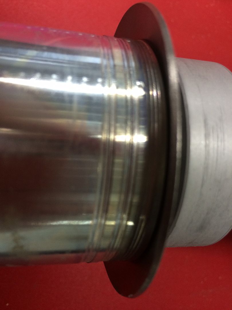
Disassemble, Permetex #3, re-assemble, test, torque, test, torque, test, torque, shims, oil seal, cam plug, gland nut, torque, test , all still OK. And that's where I stand now: the re-assembled engine turns freely and has a detectable bit of end play discernible at the prop hub. Why it was tight initially is a mystery. There is one potential clue: I noticed several groves on the prop hub under the forward case flange in front of the oil slinger. I read in the archives that others have noticed this as well, but didn't have an explanation. Seems as though the case may have 'machined' these grooves. Is this something I should be worrying about? Thanks.
- jwd3ca
- Posts: 95
- Joined: Thu Apr 10, 2014 8:56 am
Re: new AeroVee seems tight
jwd3ca wrote:There is one potential clue: I noticed several groves on the prop hub under the forward case flange in front of the oil slinger. I read in the archives that others have noticed this as well, but didn't have an explanation. Seems as though the case may have 'machined' these grooves. Is this something I should be worrying about?
Are you talking about these grooves?

If these are what you are referring to, then there's nothing to worry about. These are there on purpose. If you look closely they are actually "threads" that catch whatever oil happens to make it past the slinger ring and moves it back toward the case.
Joe Norris
Sonex N208GD (S/N 450)
Sonerai II N13NN (S/N 1206)
Fortes Fortuna Adiuvat
Sonex N208GD (S/N 450)
Sonerai II N13NN (S/N 1206)
Fortes Fortuna Adiuvat
-

Sonerai13 - Posts: 415
- Joined: Tue Nov 05, 2013 5:36 pm
- Location: Oshkosh, WI
Re: new AeroVee seems tight
Thanks, Joe, here's what mine look like.
Whew, that's a relief, I was a bit worried, thought my tightness issue might have had something to do with unintentional 'machining" of these grooves :) Not sure how I missed the fact that these are there by design...
Whew, that's a relief, I was a bit worried, thought my tightness issue might have had something to do with unintentional 'machining" of these grooves :) Not sure how I missed the fact that these are there by design...
- jwd3ca
- Posts: 95
- Joined: Thu Apr 10, 2014 8:56 am
Re: new AeroVee seems tight
It would appear that you have four more things to check for the excessive tightness of your newly built engine:
1. When you are closing the case make sure all the bearings are seated correctly and the camshaft gears line up with the crankshaft at the appropriate timing marks. Make sure none of the bearings come off their dowel pins.
2. The connecting rods are oriented correctly (double check your manual)
3. Your pistons are oriented in the correct direction. The little arrows point toward the back of the engine/flywheel/accessory plate.
4. You don't have any interference issues with the crank or rods hitting or rubbing the engine case.
Finally, you will probably want to get a new oil seal because the oil seals get distorted when you take them off.
Please keep us posted on your results. Good write up on your findings!
Jake
Sonex Tri Gear, Rotax 912 ULS, Sensenich 3 Blade Ground Adjustable Propeller
MGL Velocity EMS, Garmin GTR 200 Comm, GTX 335 ADS B Out Transponder
ILevil AW AHRS & ADS-B In, UAvionix AV20S
200+ hours previously with Aerovee engine
Sarasota, Florida
MGL Velocity EMS, Garmin GTR 200 Comm, GTX 335 ADS B Out Transponder
ILevil AW AHRS & ADS-B In, UAvionix AV20S
200+ hours previously with Aerovee engine
Sarasota, Florida
-

SonexN76ET - Posts: 494
- Joined: Tue Aug 27, 2013 2:39 pm
- Location: Atlanta
16 posts
• Page 2 of 2 • 1, 2
Who is online
Users browsing this forum: No registered users and 45 guests


