SNX-F11 Fuselage Box / Firewall Assembly
Here's another lessons learned item for the forum.
This past week when assembling the FWD fuselage, specifically the firewall, I discovered the first match hole parts that didn't match up. This is related to the small angles supplied in the kit, SNX-F14-04 R & L Firewall Attach Angle. This part comes with 3/32" pilot holes in it which are used to make the holes in the cowling attach hinge (F14-03) and Forward Angles (F14-02). As you,can see the plans have you pilot drill two other parts (and then the fwd fuselage side panels) from this one part. My side panels went together fine, and look good, but the problem came after fitting the firewall with the two required bends at top and bottom. The holes did not line up.
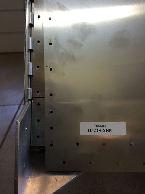
To make matters worse, I went ahead and redrilled the firewall attach angles. When I tried to fit the upper firewall cross brace (made to the plan width) the firewall pushed out and would not fit without taking the firewall apart. So consulting the plans I read 32" as the distance between the longerons. Not the outside edge of the longerons. I hooked the measuring tape on the edge of the motor mounts and it was less than 32"...thought oh I need to make it wider, which is why the cross brace is not fitting.
Long story shortened...I redrilled the firewall attach angles yet again (now three holes in these parts), and also had to redrilled the cross brace, but my overall width was now really 32-1/4". Dropped the engine mount in the airframe and there was a large gap.
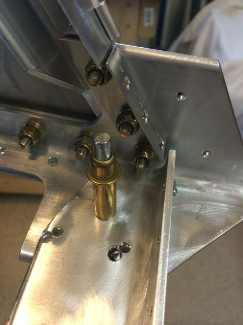
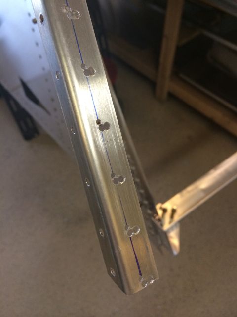
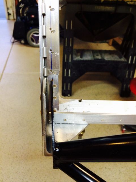
An email to Tech Support on Tuesday resulted in a response that said change the width back to 32" from outside of the longeron to outside of longeron. After doing this I felt like I was making too many compromises with a critical area of the airframe.
So, got the scrap aluminum out, took a small piece of the sheet metal to work, and asked the fab shop to shear and bend two pieces for me for new firewall attach angles. With no pilot holes! It's nice to know the guys at our R&D fabrication hand work shop.
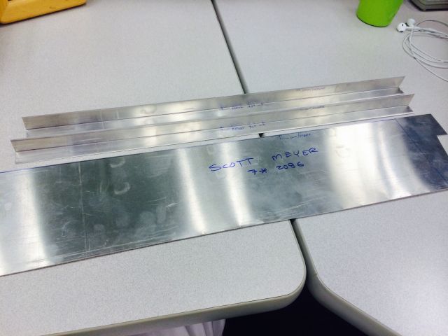
Came home from work and remade the upper firewall cross brace. Thanks to Mike F. for the use of your scrap aluminum!
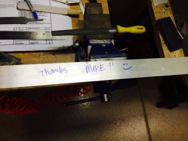
Old part and new one:
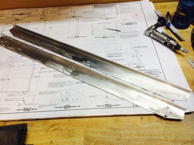
And with everything removed and new angles installed, the firewall can be used for making the pilot holes:
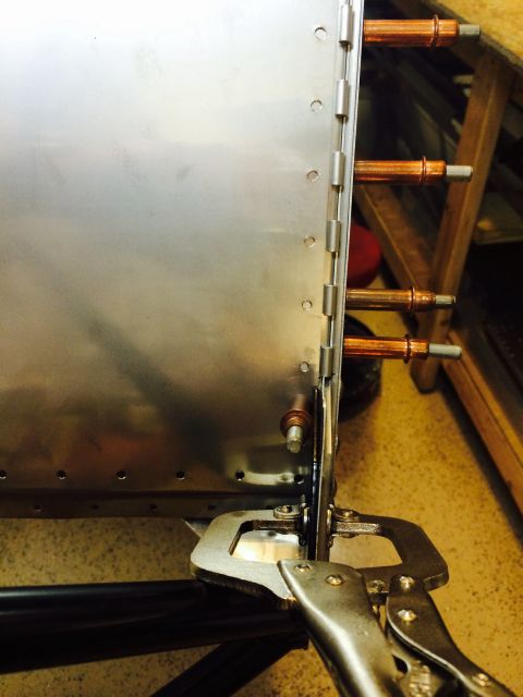
All pilot holes transferred to this new angle(s).
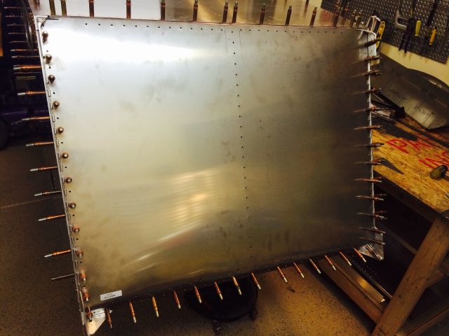
Sonex if your listening, when you make these parts F14-04 in the future, leave off the pilot holes facing the firewall. There are too many variables with the exact fit of the fwd fuselage sides and angles to have the holes exactly line up.
The other option I have considered now that I went through this learning process, would be to possibly attach the firewall to the angles before making the bends, to see if the holes will work. Or maybe wait to install the three angles that are drilled and riveted to the side panels which create the firewall attach angle until you fit the firewall. But I still think supplying this angle (F14-04) un-drilled on the firewall side the better solution.
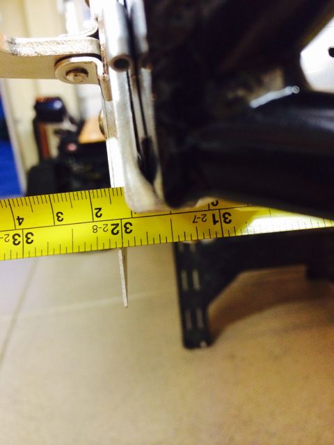
Also one last reminder. The dimension of the upper firewall can be verified by clamping the motor mount in place, and using a tape measure to read 32"!!!
This past week when assembling the FWD fuselage, specifically the firewall, I discovered the first match hole parts that didn't match up. This is related to the small angles supplied in the kit, SNX-F14-04 R & L Firewall Attach Angle. This part comes with 3/32" pilot holes in it which are used to make the holes in the cowling attach hinge (F14-03) and Forward Angles (F14-02). As you,can see the plans have you pilot drill two other parts (and then the fwd fuselage side panels) from this one part. My side panels went together fine, and look good, but the problem came after fitting the firewall with the two required bends at top and bottom. The holes did not line up.

To make matters worse, I went ahead and redrilled the firewall attach angles. When I tried to fit the upper firewall cross brace (made to the plan width) the firewall pushed out and would not fit without taking the firewall apart. So consulting the plans I read 32" as the distance between the longerons. Not the outside edge of the longerons. I hooked the measuring tape on the edge of the motor mounts and it was less than 32"...thought oh I need to make it wider, which is why the cross brace is not fitting.
Long story shortened...I redrilled the firewall attach angles yet again (now three holes in these parts), and also had to redrilled the cross brace, but my overall width was now really 32-1/4". Dropped the engine mount in the airframe and there was a large gap.


An email to Tech Support on Tuesday resulted in a response that said change the width back to 32" from outside of the longeron to outside of longeron. After doing this I felt like I was making too many compromises with a critical area of the airframe.
So, got the scrap aluminum out, took a small piece of the sheet metal to work, and asked the fab shop to shear and bend two pieces for me for new firewall attach angles. With no pilot holes! It's nice to know the guys at our R&D fabrication hand work shop.

Came home from work and remade the upper firewall cross brace. Thanks to Mike F. for the use of your scrap aluminum!

Old part and new one:

And with everything removed and new angles installed, the firewall can be used for making the pilot holes:

All pilot holes transferred to this new angle(s).

Sonex if your listening, when you make these parts F14-04 in the future, leave off the pilot holes facing the firewall. There are too many variables with the exact fit of the fwd fuselage sides and angles to have the holes exactly line up.
The other option I have considered now that I went through this learning process, would be to possibly attach the firewall to the angles before making the bends, to see if the holes will work. Or maybe wait to install the three angles that are drilled and riveted to the side panels which create the firewall attach angle until you fit the firewall. But I still think supplying this angle (F14-04) un-drilled on the firewall side the better solution.
Also one last reminder. The dimension of the upper firewall can be verified by clamping the motor mount in place, and using a tape measure to read 32"!!!
