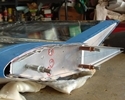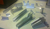


random user submitted photo
F-03
5 posts
• Page 1 of 1
F-03
There are two, 1- 3/4" holes in my -02 channel that I hope some day will become part of the rear spar carrythrough structure. Neither of which is positioned to match the dimention of 19- 9/16" to the center of the hole shown on the print. The actual dimention of the closest hole is 19" even.
I've seen posts going both ways; don't worry about it, and the hole needs to be elongated. What I've not seen, or can't find, however, is a post of the final installation with a definnative this way or that. So far, just silence on the matter from Tech Support.
There is also a notch that I am required to cut in the -02 channel, that when viewed on the print, is not only centered on the channel, but has it's centerline matched to the mythical 19 -9/16" hole. Assuming the hole is supposed to be at the 19" location that was put there by Sonex, does the notch stay centered on the channel, or does it's dimentions need to be altered to align with the centerline of the pre-punched hole?
This is just one of what seems to be many issues that should have (in my opinion) made it to the plans revisions page.
Any info is greatly appreciated.
Thanks from Area 51%
- Area 51%
- Posts: 804
- Joined: Thu Feb 18, 2016 7:57 am
Re: F-03
I can tell you in a week or two. I still have to assemble the sticks and mixer mount. I don't think it would be hard to open up after the fact so I went with "don't worry about it."
Bryan Cotton
Poplar Grove, IL C77
Waiex 191 N191YX
Taildragger, Aerovee, acro ailerons
dual sticks with sport trainer controls
Prebuilt spars and machined angle kit
Year 2 flying and approaching 200 hours December 23
Poplar Grove, IL C77
Waiex 191 N191YX
Taildragger, Aerovee, acro ailerons
dual sticks with sport trainer controls
Prebuilt spars and machined angle kit
Year 2 flying and approaching 200 hours December 23
-

Bryan Cotton - Posts: 5489
- Joined: Mon Jul 01, 2013 9:54 pm
- Location: C77
Re: F-03
The hole doesn't bother me as much as the notch. There are shear angles that straddle that notch, so it seems logical that the notch should be cut as shown on the print. On the other side, since the print can't seem to hit it's butt with both hands, I really would like confirmation that it isn't supposed to be a clearance notch for the control system somehow, and moved to the hole location.
Keep me posted Brian.
Rolling rocks uphill @ Area 51%
Keep me posted Brian.
Rolling rocks uphill @ Area 51%
- Area 51%
- Posts: 804
- Joined: Thu Feb 18, 2016 7:57 am
Re: F-03
Earlier thread on the topic:
viewtopic.php?f=15&t=2100
viewtopic.php?f=15&t=2100
Bryan Cotton
Poplar Grove, IL C77
Waiex 191 N191YX
Taildragger, Aerovee, acro ailerons
dual sticks with sport trainer controls
Prebuilt spars and machined angle kit
Year 2 flying and approaching 200 hours December 23
Poplar Grove, IL C77
Waiex 191 N191YX
Taildragger, Aerovee, acro ailerons
dual sticks with sport trainer controls
Prebuilt spars and machined angle kit
Year 2 flying and approaching 200 hours December 23
-

Bryan Cotton - Posts: 5489
- Joined: Mon Jul 01, 2013 9:54 pm
- Location: C77
Re: F-03
As it turns out, the dimension on the plans would have put the hole in the correct location. The installed rod goes through the hole that came with the part well enough, but the idler hits the edge of the hole before the up-stop is reached. It will have to be elongated.
- Area 51%
- Posts: 804
- Joined: Thu Feb 18, 2016 7:57 am
5 posts
• Page 1 of 1
Who is online
Users browsing this forum: No registered users and 1 guest


