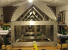


random user submitted photo
Scratch Builder Tip - Fitting Skins to Rib Flanges
1 post
• Page 1 of 1
Scratch Builder Tip - Fitting Skins to Rib Flanges
Steve Moody from the UK sent this tip along that may help scratch builders. He describes how to fit the tail skins to the underlying rib flanges without the benefit of pre-located holes in both the skin and the rib flange. Kit builders don't typically need to worry about this, but it's good info for anyone making their own new or replacement parts.
--------------
Hi Jeff, I’m not sure if the idea below is still relevant as I suspect that more modern production kits than mine, #1383, are pilot drilled in the factory on both parts, but mine were not and there may possibly be people out there with older kits.
“ How to accurately set up and drill the internal structure of a fin or horizontal tail:
The flanges on the internal channels that form the structure to hang the tail skins on are not (at least in my 2009 production kit) pilot drilled to fit the skins - which are pilot drilled and accurately shaped.
The edge distance requirements on the channel flanges require a very accurate alignment of the channels in their final layout so that when you offer up the skin you can pilot drill the blank channel flanges where the holes should be.
I realized that I had a very accurate layout of the needed channel arrangement in the factory produced skins, so....
Place and fix in place some clean paper 2” or 3” larger all round than one side of the structure you’re working on on a true flat wood surface suitable later for tapping small nails into. You’re only going to do half of the fin skin, or either the top or the bottom horizontal tail skin. Then lay the skin down on the paper with the inside of the skin facing up. Fix it in place carefully, checking that everything remains stationary.
Now mark around the outside of the skin and at each end of the lines of pilot holes extended out away from the skin. To do so lay a long ruler so it’s edge passes as closely as possible bisecting each and every pilot hole, then mark your paper out away from the skin edge along the ruler. At every 2nd or 3rd pilot hole use a sharp pencil to mark their positions, wriggling it around inside each hole.
When you now remove the skin you’re left with an accurate skin outline and markings from which you can join the rivet centrelines back to each other, checking that the lines you draw in pass directly through each pilot hole mark.
This was my fin marking paper, nearly 10 years old now, so a little tatty. It was uncreased when I was using it!
Now accurately mark on the flange edge lines using the pilot hole markings where necessary on the internal structure area. I started out trying to do so by measurement, then realized that each channel section was the perfect size to use as a 'spacing' ruler. I carefully marked the ends of each section on the inside of the flange with a fine point Sharpie at the point where the rivet line should be, then placed the section with those marks exactly over each pilot hole centreline on my paper layout, and drew the edges along each section sides.
You now have in front of you an accurate outline of the (in the photo above case) half a fin together with exactly where the flanges need to go to be under the mid line of the skin pilot holes.
The rest is straightforward, cut and shape the channel sections as per the plans dimensions if you’ve not done so already, then tack them carefully into place on your drawing using small thin pieces of oblong wood scrap, nailed to your underboard outside of the flanges, un-nailed sections over flanges, to hold them in place over the drawing. You now have the internal channel structure accurately placed to be drilled and cleco'd as per the plans.
When done remove the structure from the paper, offer it up to the appropriate side of the skin checking you’re on the inside, then clamp in place and drill at #40 through the skin pilot holes - your resulting holes should be right on each channel flange. 'Blue lining' the flanges will confirm alignment before drilling.”
Regards,
Steve Moody
Leamington Spa, England.
- sonex1374
- Posts: 605
- Joined: Thu Mar 27, 2014 1:02 am
1 post
• Page 1 of 1
Who is online
Users browsing this forum: No registered users and 12 guests


