Lift Reserve Indicator (LRI) Demonstration
The LRI is an on-again off-again topic that comes up occasionally, today I felt like making a little demonstration video of how it works in the cockpit.
https://youtu.be/7aVS91ogf1c
Video Description:
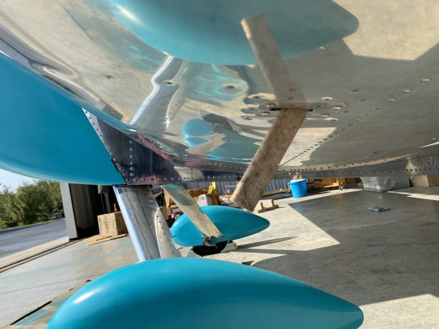
"This is a video demonstrating my Lift Reserve Indicator (LRI), which is basically a very simple/inexpensive setup that gives readout similar to an Angle of Attack (AOA) indicator. It uses 2 90-degree offset ports on a 3d-printed probe which is mounted on my left wing and set to the stall AOA, connecting to a simple differential pressure gauge. The resulting indication, once calibrated, will provide a visual indication of proximity to stall AOA, as well as how much of a buffer (reserve lift) is left between your current AOA and stall.
The demonstration shows how when the stall buffet occurs, the LRI is indicating the stall in the middle of the red arc (which happens to be where I've calibrated it), while the airspeed varies depending on how accelerated the stall is. Additionally, the landing video shows how the LRI is useful in controlling approach and touchdown airspeed. For all of these maneuvers the LRI was my primary instrument (including the landing.) Since the LRI is essentially AOA based, unlike airspeed, the readout is valid for any aircraft weight, pitch, or bank angle."
If anyone has any ideas for additional demonstrations/capabilities of LRI, let me know and I can do more testing/video. I believe is also has usefulness for setting best glide (again, at any weight), and possibly best angle of climb. I think it’s a fantastic instrument that’s also in the budget of a home builder.

