

random user submitted photo
Flush blind rivets
5 posts
• Page 1 of 1
Flush blind rivets
First off....sorry for coming to the Sonex forums even though I'm currently battling a Waiex for air supremacy. I'm told that most everything forward of the tail is common to both and am hoping for a broader range of input.
I'm currently on page F-16 (Waiex plans) and trying to get my head wrapped around the -03 aft tunnel web assembly; more specifically, the countersinking and dimpling process shown in detail "B". I have both the 120 deg. countersink and dimple dies, and have used the dimple die with success during the stabilator build.
Since I'm not an engineer, some of the symbols on the prints are new to me, but can be interpreted fairly easily. The one I can't understand is the apparent hole diameter symbol that is associated with the countersink. It shows 1/4in. for an otherwise 1/8in. hole. I'm assuming this means the top of the countersink should be 1/4in. Please let me know if this is not correct. It might be where I've gone astray. That's what I used as a dimention on a test piece of 1/8in. thick material. Next, I dimpled some .032 test material "into" the countersink as called for on the print. So far so good. When I pulled a rivet in the assembly, the head was flush as you would expect, however there seemed to be less than satisfactory tension between the two componnents; meaning I could rotate the two pieces without danger of breaking the skin on my fingers. I tried many configurations using 100/120deg. tools in every combination I could think of, including pneumatic vs. manually pulled rivets, with the same result.
Is this normal for this attachment? I prepared a 100deg. test piece and drove a solid AN rivet into it. The joint could not be turned without the use of pliers. What, if anything, am I missing, or am I worrying about nothing? This seems a very critical component, being related to the spar, and I need to obviously get it right before moving on since this technique is used elsewhere.
There is also a "note" that warns against riveting the assembly together at this stage. It references pg. F-11 for further riveting information, but near as I can tell, the web assembly is complete before it gets used there. Does anyone have any intel as to why the web should or shouldn't be riveted at this stage?
I'm inclined to use AN rivets on this assembly, unless I can figure out what I'm doing wrong with the Cherry rivets, and it would be worlds easier to rivet it on the bench now rather than during the build-up of the forward fuselage.
Thanks for the ears.
Randy here.......stuck in the mud @Area 51%
- Area 51%
- Posts: 800
- Joined: Thu Feb 18, 2016 7:57 am
Flush blind rivets
Hi Randy
I can answer why you need to wait to finish the assembly. If I am wrong I know others will correct me.
The reason you wait is because there is need later to perform work that you cannot do if the assembly has been riveted. If you read further into the plans you will discover this.
Congratulations on your progress and keep pushing on! It is so worth every minute of labor when you're flying it!
Robbie Culver
Sonex 1517
Chicagoland
N1517S
Robbie Culver
Sonex 1517
Aero Estates (T25)
First flight 10/10/2015
375+ hours
Jabiru 3300 Gen 4
Prince P Tip
Taildragger
N1517S
Sonex 1517
Aero Estates (T25)
First flight 10/10/2015
375+ hours
Jabiru 3300 Gen 4
Prince P Tip
Taildragger
N1517S
-

Sonex1517 - Posts: 1670
- Joined: Fri Jun 03, 2011 10:11 am
- Location: T25 Aero Estates, Frankston, TX
Re: Flush blind rivets
If I'm thinking of the same assembly as you are talking about you don't rivet ut together because you have to be able to remove it when drilling and rigging the wings.
Keith
#554
Keith
#554
- kmacht
- Posts: 771
- Joined: Tue Jun 21, 2011 11:30 am
Re: Flush blind rivets
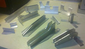
No I think he is talking about the aft web assembly, not the entire spar tunnel. The web assembly has an angle piece on top, and two angle pieces on the aft side. The reason the plans call for these to not be riveted is because there are some more holes and countersinking that needs to be done, and these holes are in a different location based on Tri Gear or Standard Gear. If you look ahead in the plans you can see what I am talking about. On the Sonex plans it is on SNX F-01. I drilled, countersunk, and riveted these angles on the aft web assembly before rigging the wings. The main thing is that you cannot rivet the aft web to the forward spar tunnel, and neither should be riveted to the wing attach angles.
- Direct C51
- Posts: 178
- Joined: Wed Jul 09, 2014 8:32 pm
Re: Flush blind rivets
Is there any reason the bottom two rivets that connect the forward tunnel Z to the forward wing attach angles shouldn't be CCPs ? The holes in the angle are so close to the longeron I can't get a countersink bit in for the CCCs. On the wing rigging page, it doesn't look like it should matter as the bottom of the spar needs to clear the longeron anyway, and these rivets are below the top edge of the longeron. On my second Waiex, I'll remember to not rivet the forward angles in place instead of just the rear, as stated on the plans.
- Area 51%
- Posts: 800
- Joined: Thu Feb 18, 2016 7:57 am
5 posts
• Page 1 of 1
Who is online
Users browsing this forum: No registered users and 67 guests


