


random user submitted photo
The VeeCU
Re: The VeeCU
![]() by WesRagle » Sun Aug 08, 2021 2:05 pm
by WesRagle » Sun Aug 08, 2021 2:05 pm
Hi Guys,
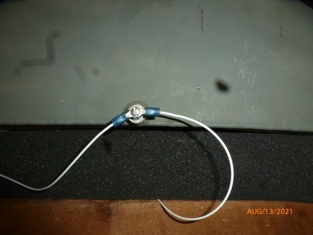
I changed to 5 Ohm coils this morning. I took another look at the voltage at the trigger input. Virtually no change.
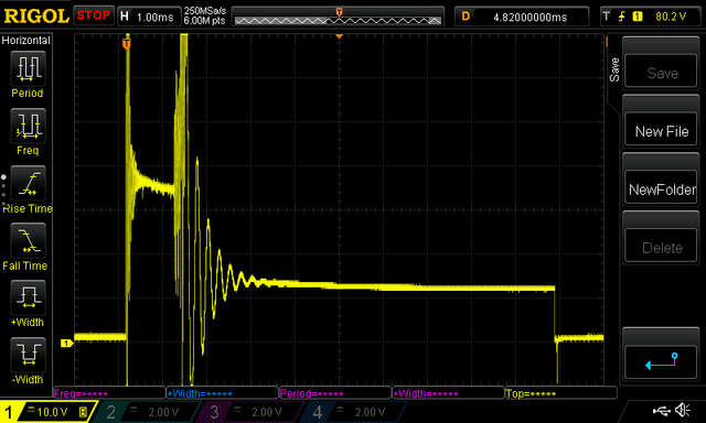
I did take the time to think about what I was looking at this time. Both plugs probably do fire at the same time. The spark lasts just about 1 mSec. When the spark stops the primary "rings" for a while and then settles in on 12V power until the trigger magnet passes at which point the secondary ignition grounds the lead again.
Wes
I changed to 5 Ohm coils this morning. I took another look at the voltage at the trigger input. Virtually no change.
I did take the time to think about what I was looking at this time. Both plugs probably do fire at the same time. The spark lasts just about 1 mSec. When the spark stops the primary "rings" for a while and then settles in on 12V power until the trigger magnet passes at which point the secondary ignition grounds the lead again.
Wes
Wes Ragle
Onex #89
Conventional Gear
Long Tips
Hummel 2400 w/Zenith Carb
Prince P Tip 54x50
First Flight 06/23/2020
42.8 Hrs. as of 10/30/21
Onex #89
Conventional Gear
Long Tips
Hummel 2400 w/Zenith Carb
Prince P Tip 54x50
First Flight 06/23/2020
42.8 Hrs. as of 10/30/21
- WesRagle
- Posts: 844
- Joined: Fri Jan 05, 2018 12:35 pm
- Location: Weatherford, Tx
Re: The VeeCU
![]() by WesRagle » Tue Aug 10, 2021 6:22 pm
by WesRagle » Tue Aug 10, 2021 6:22 pm
Hi Guys,
A little progress on the test bed today. Trying to do machine work with a ruler and hand drill takes me forever but with some persistence I managed to make the adapter plate so I could use a clamp to mount the IAT/MAP sensors.
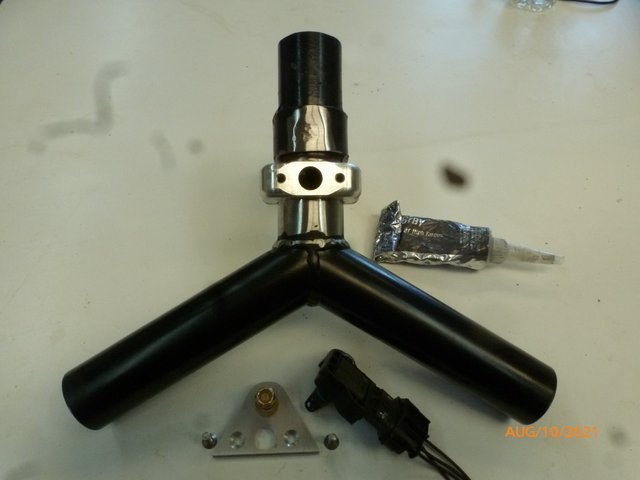
Since I started down kluge lane, I kluged in a MAP port as well (needed for the fuel pressure regulator reference). I sealed around the clamps with gasket maker and cinched the clamps down. I let them sit overnight and tighten them good in the morning. Keep in mind that this is not meant to be an airworthy setup. It's only purpose is to support development of the ECU.
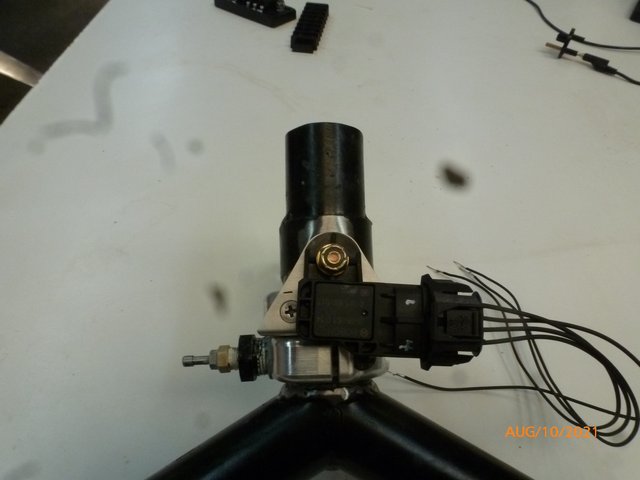
Tomorrow I'll splice onto the sensor leads and wire them over to "Mission Control" :-)
I've been thinking about how to measure engine temperature for "Warm Up Enrichment" without adding a thermocouple and all that that entails. The temperature reading doesn't have to be super accurate, just an indication of Cold, Cool, Warm, etc. Poking around I came across the "CB Performance Gen 4 EFI Installation Manual"
(Ref.http://cbperformance.net/pdf/Gen4EFI.pdf). What's shown on page 2 looks like a pretty good solution. We'll see.
Wes
A little progress on the test bed today. Trying to do machine work with a ruler and hand drill takes me forever but with some persistence I managed to make the adapter plate so I could use a clamp to mount the IAT/MAP sensors.
Since I started down kluge lane, I kluged in a MAP port as well (needed for the fuel pressure regulator reference). I sealed around the clamps with gasket maker and cinched the clamps down. I let them sit overnight and tighten them good in the morning. Keep in mind that this is not meant to be an airworthy setup. It's only purpose is to support development of the ECU.
Tomorrow I'll splice onto the sensor leads and wire them over to "Mission Control" :-)
I've been thinking about how to measure engine temperature for "Warm Up Enrichment" without adding a thermocouple and all that that entails. The temperature reading doesn't have to be super accurate, just an indication of Cold, Cool, Warm, etc. Poking around I came across the "CB Performance Gen 4 EFI Installation Manual"
(Ref.http://cbperformance.net/pdf/Gen4EFI.pdf). What's shown on page 2 looks like a pretty good solution. We'll see.
Wes
Wes Ragle
Onex #89
Conventional Gear
Long Tips
Hummel 2400 w/Zenith Carb
Prince P Tip 54x50
First Flight 06/23/2020
42.8 Hrs. as of 10/30/21
Onex #89
Conventional Gear
Long Tips
Hummel 2400 w/Zenith Carb
Prince P Tip 54x50
First Flight 06/23/2020
42.8 Hrs. as of 10/30/21
- WesRagle
- Posts: 844
- Joined: Fri Jan 05, 2018 12:35 pm
- Location: Weatherford, Tx
Re: The VeeCU
![]() by WesRagle » Thu Aug 12, 2021 2:54 pm
by WesRagle » Thu Aug 12, 2021 2:54 pm
Hi Guys,
I've reinstalled the modified induction system. Since I was still waiting on the pipes I decided to mock up the fuel system.
Since I don't like the idea of pumping 10 to 20 gallons of fuel per hour through the cockpit, I'm basing my fuel system on what Peter Henry presented with some minor modifications.
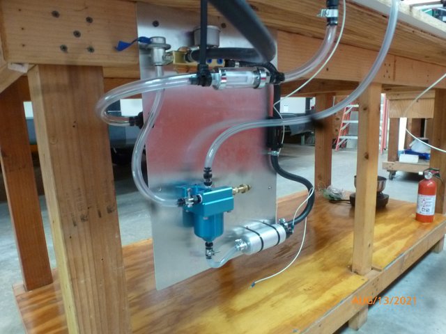
The front of the mock up:
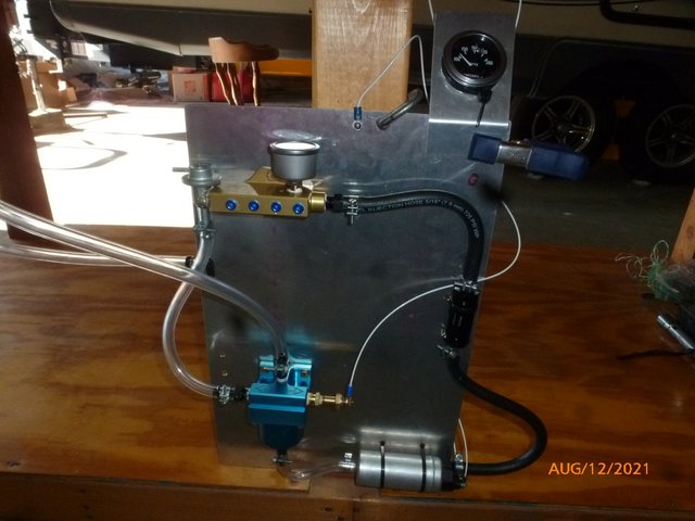
The back of the mock up:
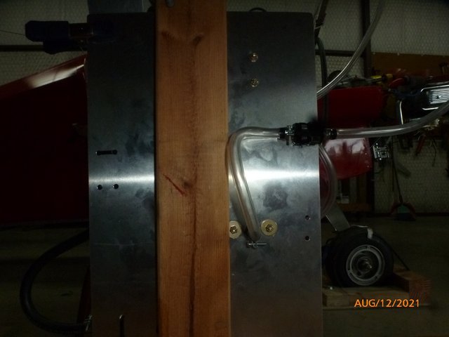
Since I couldn't find a 40 micron screen for the gascolator I caved and bought a 40 micron filter. That's it on the back of the mock up. And, since I had a 40 micron filter, I decided to plumb it before the gascolator and remove the screen from the gascolator. With that done, what was a gascolator is now just a fuel distribution manifold. After staring at my blue manifold for a while what it started to look like a pretty cool manifold with a built in miniature vented surge tank. So, that's how I plumbed it. The cheap temperature gauge, plumbed where the AeroInjector will eventually get it's fuel, was pretty useless.
I plumbed all of the low pressure lines with clear vinyl so I could watch it work. I turned the fuel on at the tank and the lines filled pretty much like you would expect with the surge tank vent filling to fuel level much like a sight gauge.
So, I applied power.
First surprise, my 3 Amp bench supply went into current limit trying to drive my 2.5 amp fuel pump. Latter measurements showed that the pump consumes 3.5 amps in the configuration shown.
OK, substitute a 10 Amp, 12V power supply and a current meter for the bench supply. Power on and away it went.
Second surprise, the fuel pressure regulator started making vapor almost immediately. The vapor beneath the regulator outlet continued to build until if spanned the length of the connection between the regulator and the blue manifold input. It doesn't show up in pictures very well but here is an attempt.
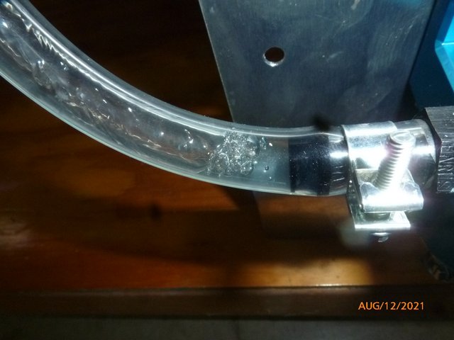
Every now and then the surge tank vent would just burp a bubble.
And no surprise, there was never any vapor at the fuel pump input.
I feel pretty good about that setup. I was hoping I wouldn't have to plumb anything back through the firewall but I think I'll have more confidence in the system if it can release vapor without passing it through the fuel pump.
After about 20 min. of continuous operation the fuel pump was too hot to hold your hand on it for over 5 seconds. The gold manifold was just a little less hot. I didn't expect it to take that long to heat up.
It might be better to move the 40 micron filter to the bottom fuel outlet. That way switching to the AeroInjector would also serve as an emergency fuel filter bypass. We'll see.
Wes
I've reinstalled the modified induction system. Since I was still waiting on the pipes I decided to mock up the fuel system.
Since I don't like the idea of pumping 10 to 20 gallons of fuel per hour through the cockpit, I'm basing my fuel system on what Peter Henry presented with some minor modifications.
The front of the mock up:
The back of the mock up:
Since I couldn't find a 40 micron screen for the gascolator I caved and bought a 40 micron filter. That's it on the back of the mock up. And, since I had a 40 micron filter, I decided to plumb it before the gascolator and remove the screen from the gascolator. With that done, what was a gascolator is now just a fuel distribution manifold. After staring at my blue manifold for a while what it started to look like a pretty cool manifold with a built in miniature vented surge tank. So, that's how I plumbed it. The cheap temperature gauge, plumbed where the AeroInjector will eventually get it's fuel, was pretty useless.
I plumbed all of the low pressure lines with clear vinyl so I could watch it work. I turned the fuel on at the tank and the lines filled pretty much like you would expect with the surge tank vent filling to fuel level much like a sight gauge.
So, I applied power.
First surprise, my 3 Amp bench supply went into current limit trying to drive my 2.5 amp fuel pump. Latter measurements showed that the pump consumes 3.5 amps in the configuration shown.
OK, substitute a 10 Amp, 12V power supply and a current meter for the bench supply. Power on and away it went.
Second surprise, the fuel pressure regulator started making vapor almost immediately. The vapor beneath the regulator outlet continued to build until if spanned the length of the connection between the regulator and the blue manifold input. It doesn't show up in pictures very well but here is an attempt.
Every now and then the surge tank vent would just burp a bubble.
And no surprise, there was never any vapor at the fuel pump input.
I feel pretty good about that setup. I was hoping I wouldn't have to plumb anything back through the firewall but I think I'll have more confidence in the system if it can release vapor without passing it through the fuel pump.
After about 20 min. of continuous operation the fuel pump was too hot to hold your hand on it for over 5 seconds. The gold manifold was just a little less hot. I didn't expect it to take that long to heat up.
It might be better to move the 40 micron filter to the bottom fuel outlet. That way switching to the AeroInjector would also serve as an emergency fuel filter bypass. We'll see.
Wes
Wes Ragle
Onex #89
Conventional Gear
Long Tips
Hummel 2400 w/Zenith Carb
Prince P Tip 54x50
First Flight 06/23/2020
42.8 Hrs. as of 10/30/21
Onex #89
Conventional Gear
Long Tips
Hummel 2400 w/Zenith Carb
Prince P Tip 54x50
First Flight 06/23/2020
42.8 Hrs. as of 10/30/21
- WesRagle
- Posts: 844
- Joined: Fri Jan 05, 2018 12:35 pm
- Location: Weatherford, Tx
Re: The VeeCU
![]() by GraemeSmith » Thu Aug 12, 2021 7:06 pm
by GraemeSmith » Thu Aug 12, 2021 7:06 pm
So is the vapor associated with the heat from the pump, or negative pressure, or both?
Can you submerge the pump in the fuel tank to keep it cool? (Not necessarily as dangerous as it sounds)
Can you submerge the pump in the fuel tank to keep it cool? (Not necessarily as dangerous as it sounds)
Graeme JW Smith
-

GraemeSmith - Posts: 939
- Joined: Sat May 18, 2019 8:58 am
- Location: RI
Re: The VeeCU
![]() by WesRagle » Thu Aug 12, 2021 11:10 pm
by WesRagle » Thu Aug 12, 2021 11:10 pm
HI Graeme,
I'm not sure whats causing it. The rate of formation isn't as strongly correlated with fuel temp as I would have expected. Some of it may just be air that was trapped in the gold manifold. When you turn the system on stone cold the down run from the fuel pressure regulator fills and then the little bubbles start forming at the regulator output until they totally fill the down run. It's funny though, the bubbles seem reluctant to enter the "blue manifold". It's almost as if the bubbles form simply as a reaction to the pressure drop and turbulence as the fuel exits the regulator.
Actually I was very happy with how long it took the fuel to heat up. What I was testing was a worst case scenario of the fuel pump left on with the engine not running. Since the volume of fuel in the closed loop is small I expected to heat rapidly. That 40 watts of power consumed by the pump ends up either heating the fuel or radiating. It looks like equilibrium is going to be reached at somewhere around 30 F. Deg above ambient. I would know better if the POS temp gauge would have worked. In normal operation, even at idle, the fuel will be changed out several times an hour so it shouldn't heat much above ambient.
I drained the system to hook up an injector. When I powered it back up the air in the system was purged quickly through the vent line. I had the end of the vent about 16" above the fuel level the air came out so quickly the vent was puking fuel. Once the air is out and the system stabilizes the fuel level in the vent line is about 1" below fuel level reflecting the slight vacuum inside the blue manifold. I'm pretty happy with the way it's working.
Now the bad news for the day. I got my pipes back from the exhaust shop. The guy at the shop bent one of the pipes and I brought it home to make sure it would work and check where I wanted the bung welded. I marked the bung on the pipe and wrote a note telling him the bung was marked on the bent pipe and to make both pipes identical. My wife was going to town to get new tires and volunteered to pick the pipes up for me. This is what she came back with.
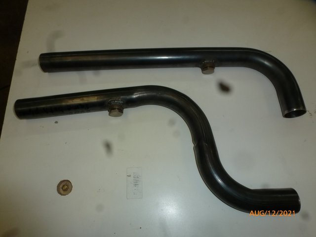
He remade a pipe out of some stock he had but it looks like the slip joint may not work. I'll check tomorrow.
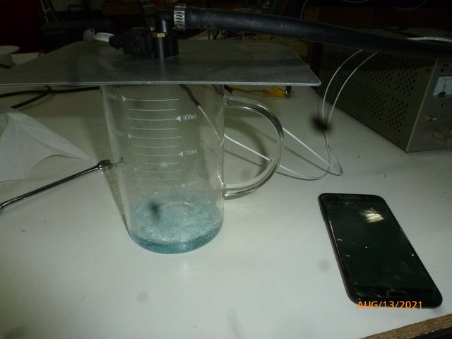
I did a flow test on one of the injectors. The seller gave the flow in grams per min. I somehow convinced myself that what they really meant was cc per min. Looks like I was wrong again. I bought 190 grams/min injectors. Here is a pic of 1 min. worth of fuel.
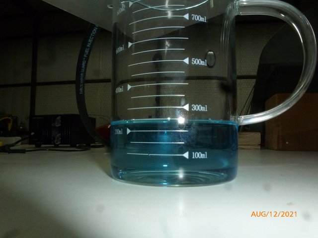
The fuel regulator that came with the gold manifold is 2.7 bar. The injectors were rated at 190 grams per min at 3 bar. The flow correction factor for differing pressures is (square root (P/P0)) Where P is the actual pressure and P0 is the referenced pressure.
So back calculating the specific gravity of the blue stuff in the beaker.
Specific Gravity = (grams/min * (square root (P/P0)))/Volume
Specific Gravity = 190 * square root (2.7/3) /250
Specific Gravity = 190 * .94 / 250
Specific Gravity = 0.7144
Sound about right? Dang it! I'm looking at 4 gal/hour per injector @ 100% duty cycle.
Anyway, minor set backs. Tomorrow is another day.
Wes
GraemeSmith wrote:So is the vapor associated with the heat from the pump, or negative pressure, or both?
I'm not sure whats causing it. The rate of formation isn't as strongly correlated with fuel temp as I would have expected. Some of it may just be air that was trapped in the gold manifold. When you turn the system on stone cold the down run from the fuel pressure regulator fills and then the little bubbles start forming at the regulator output until they totally fill the down run. It's funny though, the bubbles seem reluctant to enter the "blue manifold". It's almost as if the bubbles form simply as a reaction to the pressure drop and turbulence as the fuel exits the regulator.
GraemeSmith wrote:Can you submerge the pump in the fuel tank to keep it cool?
Actually I was very happy with how long it took the fuel to heat up. What I was testing was a worst case scenario of the fuel pump left on with the engine not running. Since the volume of fuel in the closed loop is small I expected to heat rapidly. That 40 watts of power consumed by the pump ends up either heating the fuel or radiating. It looks like equilibrium is going to be reached at somewhere around 30 F. Deg above ambient. I would know better if the POS temp gauge would have worked. In normal operation, even at idle, the fuel will be changed out several times an hour so it shouldn't heat much above ambient.
I drained the system to hook up an injector. When I powered it back up the air in the system was purged quickly through the vent line. I had the end of the vent about 16" above the fuel level the air came out so quickly the vent was puking fuel. Once the air is out and the system stabilizes the fuel level in the vent line is about 1" below fuel level reflecting the slight vacuum inside the blue manifold. I'm pretty happy with the way it's working.
Now the bad news for the day. I got my pipes back from the exhaust shop. The guy at the shop bent one of the pipes and I brought it home to make sure it would work and check where I wanted the bung welded. I marked the bung on the pipe and wrote a note telling him the bung was marked on the bent pipe and to make both pipes identical. My wife was going to town to get new tires and volunteered to pick the pipes up for me. This is what she came back with.
He remade a pipe out of some stock he had but it looks like the slip joint may not work. I'll check tomorrow.
I did a flow test on one of the injectors. The seller gave the flow in grams per min. I somehow convinced myself that what they really meant was cc per min. Looks like I was wrong again. I bought 190 grams/min injectors. Here is a pic of 1 min. worth of fuel.
The fuel regulator that came with the gold manifold is 2.7 bar. The injectors were rated at 190 grams per min at 3 bar. The flow correction factor for differing pressures is (square root (P/P0)) Where P is the actual pressure and P0 is the referenced pressure.
So back calculating the specific gravity of the blue stuff in the beaker.
Specific Gravity = (grams/min * (square root (P/P0)))/Volume
Specific Gravity = 190 * square root (2.7/3) /250
Specific Gravity = 190 * .94 / 250
Specific Gravity = 0.7144
Sound about right? Dang it! I'm looking at 4 gal/hour per injector @ 100% duty cycle.
Anyway, minor set backs. Tomorrow is another day.
Wes
Wes Ragle
Onex #89
Conventional Gear
Long Tips
Hummel 2400 w/Zenith Carb
Prince P Tip 54x50
First Flight 06/23/2020
42.8 Hrs. as of 10/30/21
Onex #89
Conventional Gear
Long Tips
Hummel 2400 w/Zenith Carb
Prince P Tip 54x50
First Flight 06/23/2020
42.8 Hrs. as of 10/30/21
- WesRagle
- Posts: 844
- Joined: Fri Jan 05, 2018 12:35 pm
- Location: Weatherford, Tx
Re: The VeeCU
![]() by GraemeSmith » Fri Aug 13, 2021 4:47 am
by GraemeSmith » Fri Aug 13, 2021 4:47 am
100LL ATSM - SG 0.68-0.74 @ STP
Graeme JW Smith
-
GraemeSmith - Posts: 939
- Joined: Sat May 18, 2019 8:58 am
- Location: RI
Re: The VeeCU
![]() by Bryan Cotton » Fri Aug 13, 2021 10:38 am
by Bryan Cotton » Fri Aug 13, 2021 10:38 am
Wes,
What fuel pressure are you running? I looked back through the thread and if it is there I missed it.
We have replaced the fuel pumps in our 80's vintage motorcycles with Holley pumps. There are solid state electronics on the pump that turn it on and off to regulate pressure. The advantage of an on-off pump is much less power demand for low flow demand. The old pumps did the same thing but had contact points in them to work.
Bryan Cotton
Poplar Grove, IL C77
Waiex 191 N191YX
Taildragger, Aerovee, acro ailerons
dual sticks with sport trainer controls
Prebuilt spars and machined angle kit
Year 2 flying and approaching 200 hours December 23
Poplar Grove, IL C77
Waiex 191 N191YX
Taildragger, Aerovee, acro ailerons
dual sticks with sport trainer controls
Prebuilt spars and machined angle kit
Year 2 flying and approaching 200 hours December 23
-

Bryan Cotton - Posts: 5071
- Joined: Mon Jul 01, 2013 9:54 pm
- Location: C77
Re: The VeeCU
![]() by WesRagle » Fri Aug 13, 2021 3:57 pm
by WesRagle » Fri Aug 13, 2021 3:57 pm
Hi Bryan,
I'm running 2.7 bar. That's what the regulator Ross provides with the "Gold Manifold" produces. A beautiful piece by the way.
I think the type of system you are describing is a returnless type. While discussing FI off line with another builder he mentioned the possibility of using PWM to control power consumption. I poked around the web for a while and came across this:
https://walbrofuelpumps.com/walbro-fuel-pump-kit-sniper-fitech-efi.html
Of particular interest is the statement:
So, I think I'll leave well enough alone and just provide whatever current the motor requires.
The burning question for me is how low can the voltage go and the pump continue to make rated pressure? I don't have the equipment to answer that question ... yet :-)
Wes
Bryan Cotton wrote:What fuel pressure are you running? I looked back through the thread and if it is there I missed it.
I'm running 2.7 bar. That's what the regulator Ross provides with the "Gold Manifold" produces. A beautiful piece by the way.
Bryan Cotton wrote:We have replaced the fuel pumps in our 80's vintage motorcycles with Holley pumps. There are solid state electronics on the pump that turn it on and off to regulate pressure. The advantage of an on-off pump is much less power demand for low flow demand. The old pumps did the same thing but had contact points in them to work.
I think the type of system you are describing is a returnless type. While discussing FI off line with another builder he mentioned the possibility of using PWM to control power consumption. I poked around the web for a while and came across this:
https://walbrofuelpumps.com/walbro-fuel-pump-kit-sniper-fitech-efi.html
Of particular interest is the statement:
This kit must always be installed with a return line to the fuel tank and may never be powered with a Pulse-Width Modulated (PWM) power source. PWM operation can seriously damage Walbro gerotor pumps. These pumps are not benefitted by PWM speed control. Simply disable the PWM feature if you are running a FiTech GoEFI system with PWM fuel pump speed control capabilities.
So, I think I'll leave well enough alone and just provide whatever current the motor requires.
The burning question for me is how low can the voltage go and the pump continue to make rated pressure? I don't have the equipment to answer that question ... yet :-)
Wes
Wes Ragle
Onex #89
Conventional Gear
Long Tips
Hummel 2400 w/Zenith Carb
Prince P Tip 54x50
First Flight 06/23/2020
42.8 Hrs. as of 10/30/21
Onex #89
Conventional Gear
Long Tips
Hummel 2400 w/Zenith Carb
Prince P Tip 54x50
First Flight 06/23/2020
42.8 Hrs. as of 10/30/21
- WesRagle
- Posts: 844
- Joined: Fri Jan 05, 2018 12:35 pm
- Location: Weatherford, Tx
Re: The VeeCU
![]() by WesRagle » Sat Aug 14, 2021 12:25 am
by WesRagle » Sat Aug 14, 2021 12:25 am
Hi Guys,
A little progress today.
I have six injectors. While set up to do so I flow checked each injector. I was pleasantly surprised that the flow of each injector is the same. Also, the resistance of the injectors is more than 12 Ohms.
I relocated the fuel system to a more permanent temporary location below the fuel tank :-)
I knocked the anatization <sp?> off of one of the plugs in the fuel tank. I drilled and tapped the plug so I could add the tank to the ground system. It all Ohm'ed out good.
I put the injectors away. The fuel pump apparently had some oily "stuff" in it when I received it. I decided to use the last of the 100 LL to flush as much of it as I could out of the system. I ran the hose that had been connected to the injectors to an old fuel can and turned the pump on. I heard the fuel pump start cavitating. A quick look showed an empty vent line. Turns out at zero pressure the fuel pump flows enough fuel to start sucking air through the vent. I hadn't considered that.
So, back out with the injectors. Hooked everything back up. I turned the pump on, waited for the system to stabilize, and marked the fuel level in the vent line. Then I turned the injector on which produces an approximate 4 gal/hour flow. I marked the new fuel level in the vent line. The 4 gal/hour flow sucked the level down about 1 1/2 inches. Assuming a linear relationship 8 gal per hour (~ max flow) would pull the level down 3 inches. If I end up installing the system I'll ensure 5 inches of head from the fuel tank outlet and the "blue manifold" vent in the three point attitude. That should allow me to run all of the fuel out of the tank without sucking air.
Edit: After thinking about it some more, it has to be the restriction of the 40 micron filter that is causing most of the suction on the vent line. I'll try moving that filter to the bottom of the "blue manifold" sometime in the future.
EDIT #2: After thinking about it even more, the 40 micron filter has to be moved downstream of the vent line else a partially clogged filter would cause the pump to suck air.
Forever Forward,
Wes
Wes Ragle
Onex #89
Conventional Gear
Long Tips
Hummel 2400 w/Zenith Carb
Prince P Tip 54x50
First Flight 06/23/2020
42.8 Hrs. as of 10/30/21
Onex #89
Conventional Gear
Long Tips
Hummel 2400 w/Zenith Carb
Prince P Tip 54x50
First Flight 06/23/2020
42.8 Hrs. as of 10/30/21
- WesRagle
- Posts: 844
- Joined: Fri Jan 05, 2018 12:35 pm
- Location: Weatherford, Tx
Re: The VeeCU
![]() by WesRagle » Tue Aug 17, 2021 9:28 pm
by WesRagle » Tue Aug 17, 2021 9:28 pm
HI Guys,
Well, the pipe the man made me from local stock to replace the one he messed up didn't work. So, new pipe on order.
Meanwhile I've been working on "Mission Control Center". Most of the wiring is done and the signals have been run to terminal strips. I pulled the fuses in the Sonerai and wired the various power switches over to the table. I'll fuse and switch them at the panel on the table. The control panel on the table is in work. Throttle cable 2 weeks out.
Wires secured:
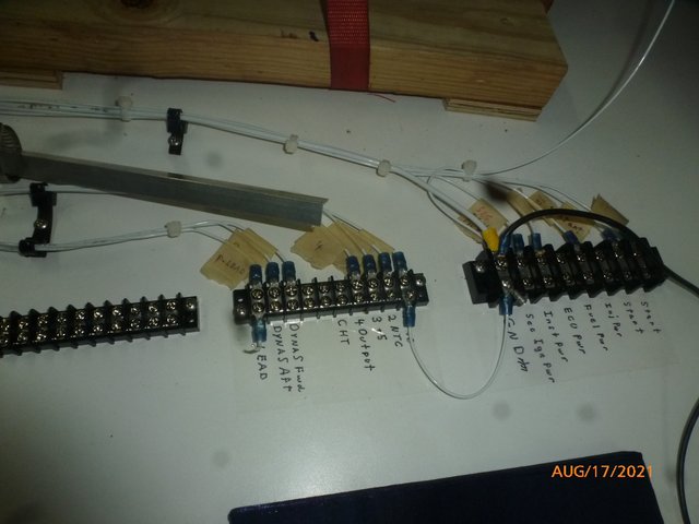
Panel in work:
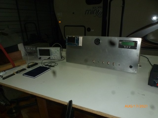
I've been obsessing over the P-Lead signal. The more I look at it the more I hate it. Noisy, high voltage, probably varies from plane to plane and engine to engine. I didn't want to but I think I'm going to cut into one phase of my alternator and get my backup signal there. The only thing the "backup signal" will be used for is to support straight batch injection in the event of a secondary ignition failure in flight.
The engine I'm working with has three identical (except for phase) signals. I wonder if someone could tell me what the AeroVee has available at the alternator output?
Thanks,
Wes
Well, the pipe the man made me from local stock to replace the one he messed up didn't work. So, new pipe on order.
Meanwhile I've been working on "Mission Control Center". Most of the wiring is done and the signals have been run to terminal strips. I pulled the fuses in the Sonerai and wired the various power switches over to the table. I'll fuse and switch them at the panel on the table. The control panel on the table is in work. Throttle cable 2 weeks out.
Wires secured:
Panel in work:
I've been obsessing over the P-Lead signal. The more I look at it the more I hate it. Noisy, high voltage, probably varies from plane to plane and engine to engine. I didn't want to but I think I'm going to cut into one phase of my alternator and get my backup signal there. The only thing the "backup signal" will be used for is to support straight batch injection in the event of a secondary ignition failure in flight.
The engine I'm working with has three identical (except for phase) signals. I wonder if someone could tell me what the AeroVee has available at the alternator output?
Thanks,
Wes
Wes Ragle
Onex #89
Conventional Gear
Long Tips
Hummel 2400 w/Zenith Carb
Prince P Tip 54x50
First Flight 06/23/2020
42.8 Hrs. as of 10/30/21
Onex #89
Conventional Gear
Long Tips
Hummel 2400 w/Zenith Carb
Prince P Tip 54x50
First Flight 06/23/2020
42.8 Hrs. as of 10/30/21
- WesRagle
- Posts: 844
- Joined: Fri Jan 05, 2018 12:35 pm
- Location: Weatherford, Tx
Who is online
Users browsing this forum: No registered users and 3 guests


