


random user submitted photo
The VeeCU
Re: The VeeCU
![]() by Dave Wolfe » Tue Dec 12, 2023 8:32 am
by Dave Wolfe » Tue Dec 12, 2023 8:32 am
Wes,
For the injectors, if you pick injectors with lower flow rates, the required current goes up. SDS indicates their system works good if you keep the minimum idle injector pulse width above 1.5 ms. With that, I get a maximum injector flow rate of 200 pph. The minimum flow rate I calculated at 14pph.
Heres what I calculated for injector current vs flow rate:
Inj Size / Duty cycle and amps
15 pph = .75. tot amps 3
20 pph .5. Tot amps 2
50 pph = .2 tot amps .8
- Dave Wolfe
- Posts: 24
- Joined: Tue Dec 31, 2019 12:40 pm
Re: The VeeCU
![]() by WesRagle » Tue Dec 12, 2023 12:20 pm
by WesRagle » Tue Dec 12, 2023 12:20 pm
Hi Dave,
I understand your point.
I am attempting to do everything "According to Hoyle". I will attempt to properly characterize the fuel injectors so that a good tune will not be affected by changing injectors. The attributes I worry about are the injector offset (open time - close time), the offset as as a function of voltage, and the non-linear section of the injector flow at low pulse width. The only thing I won't attempt to characterize is the small non-linear section of the curve.
If you take a look at this document it illustrates the above attributes of a randomly selected fuel injector.
https://cdn.shopify.com/s/files/1/0414/1681/8852/files/02J-XX-1000-X_Injector_Characterization_Summary.pdf?v=1618867983
Since those attributes are a little harder to model (may not be exact) than the static flow rate, it would be good to keep them as small a percentage of the total overall pulse width calculation as practical. To do that I want the smallest fuel injector possible (largest pulse width), without violating any other constraint.
For my particular situation, using Ross's number of .55 lb /hp/hr:
85 hp * 0.55 = 46.75 lb/hr.
To keep the duty cycle down to 75%.
46.75/0.75 = 62.33 lb/hr.
Since the mixture knob will allow you to dial in up to 1.5 times that amount, the flow goes to:
1.5 * 62.33 = 93.5 pph.
So, the minimum flow rate for each injector is:
93.5/4 = 23.375 pph.
Again, using 0.55 lb/hp/hr, at a typical cruise of maybe 50 HP you get 50 * 0.55 or 27.5 pph total or 6.875 pph/injector.
6.875/23.375 gives a duty cycle of 0.3 in cruise. Assuming 1 amp per injector that gives ~ 1.2 Amps total cruise current.
The injectors I will begin with have a static flow rate of 190 grams/min = 25.1327 pounds per hour.
Ref:https://www.aliexpress.us/item/2251832106098404.html?spm=a2g0o.detail.1000060.3.36792e41mrUtk7&gps-id=pcDetailBottomMoreThisSeller&scm=1007.13339.291025.0&scm_id=1007.13339.291025.0&scm-url=1007.13339.291025.0&pvid=52b0053d-5f15-4459-a60e-dd1973f36c8a&_t=gps-id%3ApcDetailBottomMoreThisSeller%2Cscm-url%3A1007.13339.291025.0%2Cpvid%3A52b0053d-5f15-4459-a60e-dd1973f36c8a%2Ctpp_buckets%3A668%232846%238114%231999&pdp_ext_f=%7B%22sku_id%22%3A%2264409778182%22%2C%22sceneId%22%3A%223339%22%7D&pdp_npi=2%40dis%21USD%2134.0%2132.3%21%21%21%21%21%402103222216720226395406415e5e48%2164409778182%21rec&gatewayAdapt=glo2usa
Are you running SDS EFI?
Wes
Last edited by WesRagle on Wed Dec 27, 2023 7:45 pm, edited 1 time in total.
Wes Ragle
Onex #89
Conventional Gear
Long Tips
Hummel 2400 w/Zenith Carb
Prince P Tip 54x50
First Flight 06/23/2020
42.8 Hrs. as of 10/30/21
Onex #89
Conventional Gear
Long Tips
Hummel 2400 w/Zenith Carb
Prince P Tip 54x50
First Flight 06/23/2020
42.8 Hrs. as of 10/30/21
- WesRagle
- Posts: 841
- Joined: Fri Jan 05, 2018 12:35 pm
- Location: Weatherford, Tx
Re: The VeeCU
![]() by Dave Wolfe » Tue Dec 12, 2023 1:49 pm
by Dave Wolfe » Tue Dec 12, 2023 1:49 pm
SDS is my plan. Thats a long way off at this point... Need to build wings, then tackle the engine.
Your project is looking good! Keep up with the updates.
Your project is looking good! Keep up with the updates.
- Dave Wolfe
- Posts: 24
- Joined: Tue Dec 31, 2019 12:40 pm
Re: The VeeCU
![]() by WesRagle » Wed Dec 13, 2023 9:59 am
by WesRagle » Wed Dec 13, 2023 9:59 am
Hi Dave,
Thanks for the encouragement.
I've spent the last month or so working on the hardware design. The schematic, a series of eight and a half by 11 sketches and parts lists, has been been delivered to a PCB designer. He's backed up until after Christmas. Once he gets freed up I can get a good schematic and a 3D model of the unit.
For now, I'm back on software. Until now I've been focused on signal acquisition and proper pulse generation (phasing and duration). I haven't concerned myself much with fuel and spark maps. So, that's the focus now. Fuel maps, spark maps, warm up enrichment, ...
Example of details being worked out.
Do I want to apply a one time primer pulse when I see the first blade after power is applied?
If so, how big a pulse. What are the units of a primer pulse? Can't be mSec. That would make it injector specific. Maybe a number of "cylinder fills (A/F = 14.6)" on a standard day at sea level. What is the valid range of a primer pulse? I don't know maybe 0 to 5.
Anyway, you catch my drift. I'm working on all the details that make up an engine tune.
I have all the signal inputs of the breadboard hooked up to potentiometer so I can test code on the bench as I go.
Wes
Wes Ragle
Onex #89
Conventional Gear
Long Tips
Hummel 2400 w/Zenith Carb
Prince P Tip 54x50
First Flight 06/23/2020
42.8 Hrs. as of 10/30/21
Onex #89
Conventional Gear
Long Tips
Hummel 2400 w/Zenith Carb
Prince P Tip 54x50
First Flight 06/23/2020
42.8 Hrs. as of 10/30/21
- WesRagle
- Posts: 841
- Joined: Fri Jan 05, 2018 12:35 pm
- Location: Weatherford, Tx
Re: The VeeCU
![]() by BRS » Wed Dec 13, 2023 5:41 pm
by BRS » Wed Dec 13, 2023 5:41 pm
The SDS Primer pulse is part of their accelerator pump (one in the same). With the pumps on just moving the throttle from idle to about 1/2 throttle give a little pulse through the injectors. So, for starting (in my case on an IO-360) I just need to pump the throttle three times and then hit the starter button. If it does not catch right away I do one more pump while starter is engaged. Would this work in your case?
-Brock
Sonex-A (s/n 1013)
R2300, P-tip 54/50
Center Stick
V16, TT22
Sonex-A (s/n 1013)
R2300, P-tip 54/50
Center Stick
V16, TT22
-

BRS - Posts: 365
- Joined: Thu Aug 20, 2020 4:50 pm
Re: The VeeCU
![]() by WesRagle » Wed Dec 13, 2023 7:01 pm
by WesRagle » Wed Dec 13, 2023 7:01 pm
Hey Brock,
No, no TPS. I'm focused like a laser on VW conversions with slide carbs. I didn't want to worry with trying to mount some kind of linear displacement pot.
I do intend to implement an accelerator pump function. The peripherals on the MPU really scream. All calculations will be based on the running average of the each parameter during the most recent two engine revolutions. That will be somewhere in the neighborhood of 100 to 200 samples at WOT.
All that to say that I will try using the time rate of change of MAP instead of throttle position to implement the accelerator pump.
As a side note, originally accelerator pumps were implemented in carbs (also in throttle body injection) to replenish the lost fuel on a wetted intake under rapid acceleration. If the data acquisition is responsive enough, port fuel injection shouldn't need much of an accelerator pump. All of this from books. I'll have to verify it. That's part of the fun :-)
Wes
Last edited by WesRagle on Wed Dec 27, 2023 7:48 pm, edited 1 time in total.
Wes Ragle
Onex #89
Conventional Gear
Long Tips
Hummel 2400 w/Zenith Carb
Prince P Tip 54x50
First Flight 06/23/2020
42.8 Hrs. as of 10/30/21
Onex #89
Conventional Gear
Long Tips
Hummel 2400 w/Zenith Carb
Prince P Tip 54x50
First Flight 06/23/2020
42.8 Hrs. as of 10/30/21
- WesRagle
- Posts: 841
- Joined: Fri Jan 05, 2018 12:35 pm
- Location: Weatherford, Tx
Re: The VeeCU
![]() by WesRagle » Thu Dec 21, 2023 5:17 pm
by WesRagle » Thu Dec 21, 2023 5:17 pm
Hi Guys,
The list is a little slow today so I'll jabber some.
For those interested in EFI:
The genesis for the VeeCU was the podcast : http://www.sonexflight.com/58/index.html . It's very interesting and informative. Highly recommended. It got me fired up :-)
When I first started down this road I bought any and every book I thought was relevant to EFI.
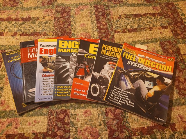
Some of them are useless, some are OK, and one is excellent.
If you are interested in EFI I highly recommend this book.
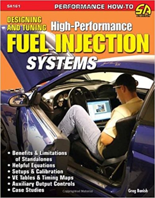
The author is an OEM tuner by day and a performance tuner by night. An easy read and mixes theory and practice of engine tuning nicely.
As for the VeeCU project, I've been working on memory layout. I'm keeping things as simple as possible. As of right now here is what an engine tune will look like. It won't format right when posted, but you get the idea.
eTuneTypeDef eTuneType; // Version of the tune template.
char cTuneName[80]; // The name ex. "High Compression Hummel 2400".
uint16_t u16TotDisplacement; // Total displacement in cc.
uint16_t u16ComRatio; // Compression ratio * 100.
bool bIsTurboed; // True if turbo charged.
uint8_t u8AltPPR; // Alternator pulses per revolution.
int16_t as16RPM [RPM_POINTS]; // RPM break points for the VE and Spark tables.
int16_t as16Spark [RPM_POINTS]; // Ignition advance at RPM points.
int16_t as16VE [RPM_POINTS]; // Volumetric efficiency at RPM points.
int16_t as16EngTemp [TEMP_POINTS]; // Temp break points for warm up enrichment.
int16_t as16CSEnrich [TEMP_POINTS]; // Enrichment Pcnt. * 10 for warm up enrichment.
int16_t s16Cyl1Trim; // Percent * 10 Trim for cylinder 1.
int16_t s16Cyl2Trim; // Percent * 10 Trim for cylinder 2.
int16_t s16Cyl3Trim; // Percent * 10 Trim for cylinder 3.
int16_t s16Cyl4Trim; // Percent * 10 Trim for cylinder 4.
uint16_t u16FuelPressure; // Fuel Pressure regulator in mBar.
uint16_t u16FuelCutRpm; // RPM for over speed fuel cut.
uint8_t u8PrimerSize; // # of cyl fills for primer pulse.
uint16_t u16APSens; // Sensitivity of Accel Pump.
The unit can store any number of tunes.
For you C afficionados, anything I forgot?
Oh yea, I spoke with Peter Van Schalkwyk and he said he didn't have a throttle position sensor on his second SDS EFI VW aircraft and he didn't notice any difference with out the accelerator pump function. For starting, he said if the engine didn't fire immediately he would use the mixture knob to add more fuel.
Wes.
The list is a little slow today so I'll jabber some.
For those interested in EFI:
The genesis for the VeeCU was the podcast : http://www.sonexflight.com/58/index.html . It's very interesting and informative. Highly recommended. It got me fired up :-)
When I first started down this road I bought any and every book I thought was relevant to EFI.
Some of them are useless, some are OK, and one is excellent.
If you are interested in EFI I highly recommend this book.
The author is an OEM tuner by day and a performance tuner by night. An easy read and mixes theory and practice of engine tuning nicely.
As for the VeeCU project, I've been working on memory layout. I'm keeping things as simple as possible. As of right now here is what an engine tune will look like. It won't format right when posted, but you get the idea.
eTuneTypeDef eTuneType; // Version of the tune template.
char cTuneName[80]; // The name ex. "High Compression Hummel 2400".
uint16_t u16TotDisplacement; // Total displacement in cc.
uint16_t u16ComRatio; // Compression ratio * 100.
bool bIsTurboed; // True if turbo charged.
uint8_t u8AltPPR; // Alternator pulses per revolution.
int16_t as16RPM [RPM_POINTS]; // RPM break points for the VE and Spark tables.
int16_t as16Spark [RPM_POINTS]; // Ignition advance at RPM points.
int16_t as16VE [RPM_POINTS]; // Volumetric efficiency at RPM points.
int16_t as16EngTemp [TEMP_POINTS]; // Temp break points for warm up enrichment.
int16_t as16CSEnrich [TEMP_POINTS]; // Enrichment Pcnt. * 10 for warm up enrichment.
int16_t s16Cyl1Trim; // Percent * 10 Trim for cylinder 1.
int16_t s16Cyl2Trim; // Percent * 10 Trim for cylinder 2.
int16_t s16Cyl3Trim; // Percent * 10 Trim for cylinder 3.
int16_t s16Cyl4Trim; // Percent * 10 Trim for cylinder 4.
uint16_t u16FuelPressure; // Fuel Pressure regulator in mBar.
uint16_t u16FuelCutRpm; // RPM for over speed fuel cut.
uint8_t u8PrimerSize; // # of cyl fills for primer pulse.
uint16_t u16APSens; // Sensitivity of Accel Pump.
The unit can store any number of tunes.
For you C afficionados, anything I forgot?
Oh yea, I spoke with Peter Van Schalkwyk and he said he didn't have a throttle position sensor on his second SDS EFI VW aircraft and he didn't notice any difference with out the accelerator pump function. For starting, he said if the engine didn't fire immediately he would use the mixture knob to add more fuel.
Wes.
Wes Ragle
Onex #89
Conventional Gear
Long Tips
Hummel 2400 w/Zenith Carb
Prince P Tip 54x50
First Flight 06/23/2020
42.8 Hrs. as of 10/30/21
Onex #89
Conventional Gear
Long Tips
Hummel 2400 w/Zenith Carb
Prince P Tip 54x50
First Flight 06/23/2020
42.8 Hrs. as of 10/30/21
- WesRagle
- Posts: 841
- Joined: Fri Jan 05, 2018 12:35 pm
- Location: Weatherford, Tx
Re: The VeeCU
![]() by WesRagle » Mon Jan 29, 2024 2:53 pm
by WesRagle » Mon Jan 29, 2024 2:53 pm
HI Guys,
Here is a link to a web site that actually provides some specifications for the sensors they sell.
Ref. https://www.bmotorsports.com/shop/index.php/cPath/129?osCsid=p2r9p1f7qf76k3afa1vuislj27.
In the interest of long term availability and universal applicability, I've decided to go with this 2 bar sensor.
Ref. https://www.bmotorsports.com/shop/product_info.php/cPath/129_143/products_id/1582?osCsid=p2r9p1f7qf76k3afa1vuislj27
Wes
Wes Ragle
Onex #89
Conventional Gear
Long Tips
Hummel 2400 w/Zenith Carb
Prince P Tip 54x50
First Flight 06/23/2020
42.8 Hrs. as of 10/30/21
Onex #89
Conventional Gear
Long Tips
Hummel 2400 w/Zenith Carb
Prince P Tip 54x50
First Flight 06/23/2020
42.8 Hrs. as of 10/30/21
- WesRagle
- Posts: 841
- Joined: Fri Jan 05, 2018 12:35 pm
- Location: Weatherford, Tx
Re: The VeeCU
![]() by WesRagle » Tue Jan 30, 2024 5:59 pm
by WesRagle » Tue Jan 30, 2024 5:59 pm
Hi Guys,
The PCB designer on this project has generated a preliminary schematic of the VeeCU and has estimated the required board area. I can now proceed with enclosure selection.
The unit is being designed for mounting on the engine side of the firewall. That requires that the unit be semi-sealed. To keep cost down a commercial off the shelf (COTS) enclosure and cable system will be used. See attached. It looks like the enclosure, connector, and mating connectors will add about $100 to the Bill of Materials. As a side note, I found a "Hydro-Phobic" patch to keep fluids from entering the vent hole.
https://www.interstatesp.com/products/vents/.
Right now I'm defining the Pin-Out. I want to design the simplest, from a users point of view, Speed-Density EFII system possible. Toward that end I would like the unit to be usable without an intelligent control head. I do have a CAN bus and an RS232 interface which will allow for tuning via a laptop or an intelligent control head in the future, but for now I would like to "Keep it simple".
So the question is: "What is the minimum interface required for operation?".
I envision:
1) A mixture knob.
2) Four SPDT Center off momentary switches for cylinder trim.
3) A single red LED to report system status.
4) Maybe a Store switch to make trim changes "permanent".
I could use a POT with an OFF switch, similar to a volume knob, which would allow the user to turn the injectors off as part of the shut down procedure. Or I could just let the installer wire the injector power on a separate switch if that function was desired.
Does that sound reasonable? What am I forgetting? Any thoughts?
Thanks,
Wes
- Attachments
-
 dr-CCS-ICE-5810148009-10-1551288.pdf
- The Connector
- (376.55 KiB) Downloaded 202 times
-
- dr-CCS-ICE-5810130065-75-1551287.pdf
- The Enclosure
- (595.59 KiB) Downloaded 215 times
Wes Ragle
Onex #89
Conventional Gear
Long Tips
Hummel 2400 w/Zenith Carb
Prince P Tip 54x50
First Flight 06/23/2020
42.8 Hrs. as of 10/30/21
Onex #89
Conventional Gear
Long Tips
Hummel 2400 w/Zenith Carb
Prince P Tip 54x50
First Flight 06/23/2020
42.8 Hrs. as of 10/30/21
- WesRagle
- Posts: 841
- Joined: Fri Jan 05, 2018 12:35 pm
- Location: Weatherford, Tx
Re: The VeeCU
![]() by WesRagle » Sat Feb 24, 2024 11:30 pm
by WesRagle » Sat Feb 24, 2024 11:30 pm
Hi Guys,
I've gotten some more time in on this project.
As a side note, when I started looking at fuel injection systems I was intimidated. So, when I started down the path of building my own ECU my vision was to produce a simple to use and simple to understand system. It's normal while designing such a device to dream/muse about solving all problems of all engines. However, if you go down that path you will never finish. So, the VeeCU is being designed to work only on VW's with Open Collector/Open Drain secondary ignition systems like the Dyna S ignition on my Hummel, and I assume like the secondary ignition on the AeroVee . I also want the unit to be simple to install. So, the existing ignition system components are used for both spark and timing. The only sensors used are MAP, Engine Temp (for warm up enrichment), and inlet air temperature. That's about $100 in sensors.
Having said that, some of the following will make more sense.
I've laid out the memory in such a way as to future proof the design as much as possible. The MCU has tons of FLASH (non-volatile) memory. Some of the memory will be used to store a data base of known good tunes. The vision is that as the VW fliers generate good tunes, those tunes will become a permanent part of the VeeCU program. There will also be a data base of tested/verified injectors. So, an initial tune will consist of selecting the tune of an engine similar to/exactly like yours and picking from the approved injector list. We'll see.
It may seem odd, but implementing the tune is close to the final step in the software development process. There is a lot of head scratching that comes first. I've finally gotten around to implementing the tune.
To use the VeeCU, the secondary ignition is retarded to 3 Deg AFTER top dead center. The secondary ignition output is routed to the VeeCU used as a timing pulse. An output of the VCU is routed to the ignition coils and provides spark control. Right now I am simulating the timing pulses with a signal generator. The positive edge is assumed to be the forward ignition and the negative edge is assumed to be the aft ignition pulse.
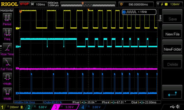
As it turns out, starting the engine is the more difficult part to get right. Here is a pic of the forward signals as the signal generator is sweeping from 1 Hz (60 RPM) to 15 Hz (900 RPM) in one second, simulating a start. The yellow trace is the timing pulses The light blue trace is the ignition signal. The coil fires on the falling edge of that signal. As shown, while the engine is cranking (RPM < 450) the system acts as an impulse mag. That is the spark fires when the timing pulse hits, 3 deg. ATDC. As the engine moves from cranking to starting, timing is taken from the table in the tune. One of the few serendipitious things is that changing the idle state of the ignition timer output from high (for impulse) to low (for dwell control) causes the coil to fire. So, I don't have to do anything hokey to get the last TDC fire before changing to timing/dwell control. You can also see where the initial dwell is much longer than the final dwell. That's because the engine will try to "run over" the timing pulse as it accelerates rapidly from starting to run. Worst case, if the engine starts very fast, the effect will be timing is retarded to TDC. As the engine reaches steady idle the dwell is further reduced to the 12 mSec recommended by Dyna Tec.
The dark blue trace shows the injector pulses. If you look closely you can see the phase changes as the engine accelerates to run. That's because during cranking and starting the pulse is phased to hit an open intake valve (half the time, remember wasted spark/semi-sequential). Everything I've read says to aim at a closed valve during run. That will allow the fuel to fully vaporize/evaporate against a hot valve and hopefully provide better cylinder head cooling by evaporating a gallon of fuel per hour on each head.
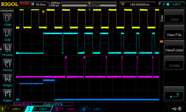
Here is a pic generated by powering on the VeeCu while the input signal is at 15 Hz (900 RPM). The yellow trace is the timing pulses. The light blue line is the ignition pulses. The magenta trace is fuel injection pulses. The dark blue line is /OE. No output will be delivered to the coils or injectors if /OE is high. /OE will not be driven low until two blades are seen. It's just to insure that the ignition coils aren't energized if the prop happens to stop right at the edge of one of the hall effect sensors. Another nuance is that fuel will not be injected unless a pulse has been seen on the "other" coil since last time fuel was injected by "this" coil. The first ignition pulse is generated as if the engine was cranking. That's because it takes two pulses to calculate an RPM so it can be determined that the engine is running.
You can also see where the first two injector pulses are wider than the others. That is the primer fuel being added to the calculated fuel quantity. The primer pulse(s) are calculated by multiplying the pulse width of the normal fuel pulse by two. Again you see two due to wasted spark. Calculating prime this way naturally causes the primer amount to increase due to "warm up enrichment", low OAT, and rich mixture setting. The two double wide pulses are the result of one (1) being set as the prime value in the tune. If two was set you would see four double wide pulses.
And lastly, a pic of me cruising at 3000 RPM with all input parameters pretty much normal :-)
The first injector in the data base is the one I selected for my plane. As can be seen, the injector duty cycle is right at 20% in cruise. The only way to saturate the injector is to fly at red line with very cold cylinder heads, very cold IAT, and the mixture set full rich. While looking at the yellow timing trace, roughly speaking, the top part of the trace is while the piston is going down and the bottom part of the trace is while the piston is moving up. You can see that the injection pulses occur while the piston is moving up during both the exhaust and compression stroke, so the intake valve is closed during the injection. You can also see that the ignition is advanced 26 Deg (based on the tune). One last thing, you can see the constant 12 mSec dwell.
All of the injection and ignition pulses are hitting within 10 micro-seconds of target. That's within 0.2 angular deg at red line. I do have one more somewhat big thing left to implement. Since our alternator is fixed to the crank it can be used as a timing source in the event of timing signal lost from the Dyna S. The phase relation will be determined after the engine is in run state. I've already done this once but it got too ugly. I now understand how to implement the feature with minimal impact on the remainder of the software.
Forever Forward,
Wes
I've gotten some more time in on this project.
As a side note, when I started looking at fuel injection systems I was intimidated. So, when I started down the path of building my own ECU my vision was to produce a simple to use and simple to understand system. It's normal while designing such a device to dream/muse about solving all problems of all engines. However, if you go down that path you will never finish. So, the VeeCU is being designed to work only on VW's with Open Collector/Open Drain secondary ignition systems like the Dyna S ignition on my Hummel, and I assume like the secondary ignition on the AeroVee . I also want the unit to be simple to install. So, the existing ignition system components are used for both spark and timing. The only sensors used are MAP, Engine Temp (for warm up enrichment), and inlet air temperature. That's about $100 in sensors.
Having said that, some of the following will make more sense.
I've laid out the memory in such a way as to future proof the design as much as possible. The MCU has tons of FLASH (non-volatile) memory. Some of the memory will be used to store a data base of known good tunes. The vision is that as the VW fliers generate good tunes, those tunes will become a permanent part of the VeeCU program. There will also be a data base of tested/verified injectors. So, an initial tune will consist of selecting the tune of an engine similar to/exactly like yours and picking from the approved injector list. We'll see.
It may seem odd, but implementing the tune is close to the final step in the software development process. There is a lot of head scratching that comes first. I've finally gotten around to implementing the tune.
To use the VeeCU, the secondary ignition is retarded to 3 Deg AFTER top dead center. The secondary ignition output is routed to the VeeCU used as a timing pulse. An output of the VCU is routed to the ignition coils and provides spark control. Right now I am simulating the timing pulses with a signal generator. The positive edge is assumed to be the forward ignition and the negative edge is assumed to be the aft ignition pulse.
As it turns out, starting the engine is the more difficult part to get right. Here is a pic of the forward signals as the signal generator is sweeping from 1 Hz (60 RPM) to 15 Hz (900 RPM) in one second, simulating a start. The yellow trace is the timing pulses The light blue trace is the ignition signal. The coil fires on the falling edge of that signal. As shown, while the engine is cranking (RPM < 450) the system acts as an impulse mag. That is the spark fires when the timing pulse hits, 3 deg. ATDC. As the engine moves from cranking to starting, timing is taken from the table in the tune. One of the few serendipitious things is that changing the idle state of the ignition timer output from high (for impulse) to low (for dwell control) causes the coil to fire. So, I don't have to do anything hokey to get the last TDC fire before changing to timing/dwell control. You can also see where the initial dwell is much longer than the final dwell. That's because the engine will try to "run over" the timing pulse as it accelerates rapidly from starting to run. Worst case, if the engine starts very fast, the effect will be timing is retarded to TDC. As the engine reaches steady idle the dwell is further reduced to the 12 mSec recommended by Dyna Tec.
The dark blue trace shows the injector pulses. If you look closely you can see the phase changes as the engine accelerates to run. That's because during cranking and starting the pulse is phased to hit an open intake valve (half the time, remember wasted spark/semi-sequential). Everything I've read says to aim at a closed valve during run. That will allow the fuel to fully vaporize/evaporate against a hot valve and hopefully provide better cylinder head cooling by evaporating a gallon of fuel per hour on each head.
Here is a pic generated by powering on the VeeCu while the input signal is at 15 Hz (900 RPM). The yellow trace is the timing pulses. The light blue line is the ignition pulses. The magenta trace is fuel injection pulses. The dark blue line is /OE. No output will be delivered to the coils or injectors if /OE is high. /OE will not be driven low until two blades are seen. It's just to insure that the ignition coils aren't energized if the prop happens to stop right at the edge of one of the hall effect sensors. Another nuance is that fuel will not be injected unless a pulse has been seen on the "other" coil since last time fuel was injected by "this" coil. The first ignition pulse is generated as if the engine was cranking. That's because it takes two pulses to calculate an RPM so it can be determined that the engine is running.
You can also see where the first two injector pulses are wider than the others. That is the primer fuel being added to the calculated fuel quantity. The primer pulse(s) are calculated by multiplying the pulse width of the normal fuel pulse by two. Again you see two due to wasted spark. Calculating prime this way naturally causes the primer amount to increase due to "warm up enrichment", low OAT, and rich mixture setting. The two double wide pulses are the result of one (1) being set as the prime value in the tune. If two was set you would see four double wide pulses.
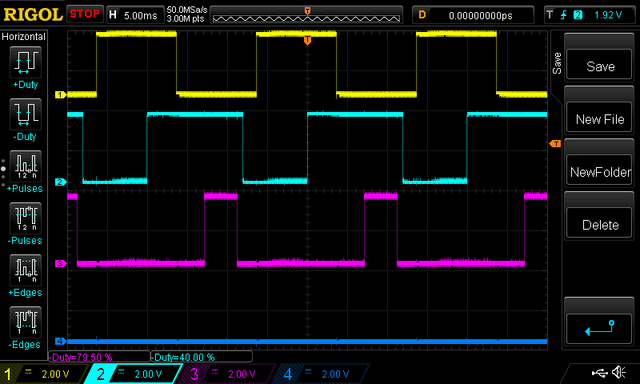
And lastly, a pic of me cruising at 3000 RPM with all input parameters pretty much normal :-)
The first injector in the data base is the one I selected for my plane. As can be seen, the injector duty cycle is right at 20% in cruise. The only way to saturate the injector is to fly at red line with very cold cylinder heads, very cold IAT, and the mixture set full rich. While looking at the yellow timing trace, roughly speaking, the top part of the trace is while the piston is going down and the bottom part of the trace is while the piston is moving up. You can see that the injection pulses occur while the piston is moving up during both the exhaust and compression stroke, so the intake valve is closed during the injection. You can also see that the ignition is advanced 26 Deg (based on the tune). One last thing, you can see the constant 12 mSec dwell.
All of the injection and ignition pulses are hitting within 10 micro-seconds of target. That's within 0.2 angular deg at red line. I do have one more somewhat big thing left to implement. Since our alternator is fixed to the crank it can be used as a timing source in the event of timing signal lost from the Dyna S. The phase relation will be determined after the engine is in run state. I've already done this once but it got too ugly. I now understand how to implement the feature with minimal impact on the remainder of the software.
Forever Forward,
Wes
Wes Ragle
Onex #89
Conventional Gear
Long Tips
Hummel 2400 w/Zenith Carb
Prince P Tip 54x50
First Flight 06/23/2020
42.8 Hrs. as of 10/30/21
Onex #89
Conventional Gear
Long Tips
Hummel 2400 w/Zenith Carb
Prince P Tip 54x50
First Flight 06/23/2020
42.8 Hrs. as of 10/30/21
- WesRagle
- Posts: 841
- Joined: Fri Jan 05, 2018 12:35 pm
- Location: Weatherford, Tx
Who is online
Users browsing this forum: No registered users and 1 guest


