


random user submitted photo
The VeeCU
Re: The VeeCU
![]() by WesRagle » Sun Feb 25, 2024 10:10 pm
by WesRagle » Sun Feb 25, 2024 10:10 pm
Hi Guys,
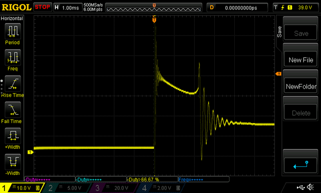
Just implemented the rev limiter. This pic shows the /OE (Output Enable Bar) disabling spark and fuel. /OE is the bottom trace. Outputs are disabled while /OE is high. The rev limit comes from the tune. For the Hummel, published red line of 3600 RPM, I'll set the rev limit to 3800. The hysteresis if fixed at 100 RPM. So, once the outputs have been disabled they will not be re-enabled until the RPM drops 100 RPM.
This pic was generated by sweeping the input up and down across the limit and repeating every 0.2 Sec. The limiter runs asynchronously to the trigger pulses. But, since the engine control IC performs soft shutdown of the ignition, no harm no foul. This is a harsh way to rev limit. It would be much kinder to limit RPM by retarding the timing. However there is probably a fixed primary ignition running so that won't work.
Wes
Wes Ragle
Onex #89
Conventional Gear
Long Tips
Hummel 2400 w/Zenith Carb
Prince P Tip 54x50
First Flight 06/23/2020
42.8 Hrs. as of 10/30/21
Onex #89
Conventional Gear
Long Tips
Hummel 2400 w/Zenith Carb
Prince P Tip 54x50
First Flight 06/23/2020
42.8 Hrs. as of 10/30/21
- WesRagle
- Posts: 841
- Joined: Fri Jan 05, 2018 12:35 pm
- Location: Weatherford, Tx
Re: The VeeCU
![]() by WesRagle » Mon Feb 26, 2024 10:37 pm
by WesRagle » Mon Feb 26, 2024 10:37 pm
HI Guys,
My "Pic of the day":-)
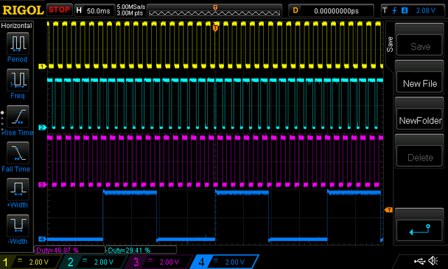
This pic shows individual cylinder trim on all 4 cylinders. I manipulated the inputs so that the untrimmed duty cycle of the injector pulses was 50%. The injectors are "ON" while the signals are high.
I pared the injectors for the front two cylinders on the top two traces. The bottom two traces are the aft cylinders. In operation the trim will be limited to +- 20.0 % but I killed the limit while testing. The first trace shows a cylinder trimmed to 0.0%. The second trace shows that cylinders mate cylinder trimmed to +50.0%. The third trace shows the first cylinders of the other pair trimmed to 0.0%. The forth trace shows it's mate trimmed to -50.0%. I don't have enough inputs on the scope to show the phase relation of the injector pulses to the timing pulses, but the pulses are all timed to end at the same phase BTDC. And of course trace #1 and #3 are 180 deg out of phase.
If the pic is clear enough to see the grids on the scope screen, you will be able to tell that the second trace is just shy of 1.5 x the length of the first trace. That is because the injector offset (open time - close time) is only applied once.
I also applied limits to all of the inputs, in part to detect sensor faults. Of course the sensor that worries me the most is the MAP sensor. That got me to thinking (maybe too much), ....
What if when the MAP sensor fails, instead of defaulting to a set value, I calculate a value based on RPM? If there was a small table that correlated MAP to RPM near ground level where ever you fly most, that would eliminate a lot of my concern about the MAP sensor failing during takeoff or landing. If the sensor happened to fail at high altitude, the panel light would indicate the sensor had failed and the mixture knob could be used to lean things back out. You would then have to walk the airplane back down by adding fuel with the mixture knob as you descend. Of course this would only work with a fixed pitch prop. Hmmm...
I have to get back on the hardware now. I need to do a final, thorough review of the schematic before PCB layout begins. There are currently two non FI/IGNITION outputs. One for simulated FF and one to de-energize the fuel pump relay if the RPM transits from run to stopped very quickly. I'm thinking of adding an RPM output, just for convenience.
Thanks,
Wes
My "Pic of the day":-)
This pic shows individual cylinder trim on all 4 cylinders. I manipulated the inputs so that the untrimmed duty cycle of the injector pulses was 50%. The injectors are "ON" while the signals are high.
I pared the injectors for the front two cylinders on the top two traces. The bottom two traces are the aft cylinders. In operation the trim will be limited to +- 20.0 % but I killed the limit while testing. The first trace shows a cylinder trimmed to 0.0%. The second trace shows that cylinders mate cylinder trimmed to +50.0%. The third trace shows the first cylinders of the other pair trimmed to 0.0%. The forth trace shows it's mate trimmed to -50.0%. I don't have enough inputs on the scope to show the phase relation of the injector pulses to the timing pulses, but the pulses are all timed to end at the same phase BTDC. And of course trace #1 and #3 are 180 deg out of phase.
If the pic is clear enough to see the grids on the scope screen, you will be able to tell that the second trace is just shy of 1.5 x the length of the first trace. That is because the injector offset (open time - close time) is only applied once.
I also applied limits to all of the inputs, in part to detect sensor faults. Of course the sensor that worries me the most is the MAP sensor. That got me to thinking (maybe too much), ....
What if when the MAP sensor fails, instead of defaulting to a set value, I calculate a value based on RPM? If there was a small table that correlated MAP to RPM near ground level where ever you fly most, that would eliminate a lot of my concern about the MAP sensor failing during takeoff or landing. If the sensor happened to fail at high altitude, the panel light would indicate the sensor had failed and the mixture knob could be used to lean things back out. You would then have to walk the airplane back down by adding fuel with the mixture knob as you descend. Of course this would only work with a fixed pitch prop. Hmmm...
I have to get back on the hardware now. I need to do a final, thorough review of the schematic before PCB layout begins. There are currently two non FI/IGNITION outputs. One for simulated FF and one to de-energize the fuel pump relay if the RPM transits from run to stopped very quickly. I'm thinking of adding an RPM output, just for convenience.
Thanks,
Wes
Wes Ragle
Onex #89
Conventional Gear
Long Tips
Hummel 2400 w/Zenith Carb
Prince P Tip 54x50
First Flight 06/23/2020
42.8 Hrs. as of 10/30/21
Onex #89
Conventional Gear
Long Tips
Hummel 2400 w/Zenith Carb
Prince P Tip 54x50
First Flight 06/23/2020
42.8 Hrs. as of 10/30/21
- WesRagle
- Posts: 841
- Joined: Fri Jan 05, 2018 12:35 pm
- Location: Weatherford, Tx
Re: The VeeCU
![]() by WesRagle » Wed Feb 28, 2024 7:00 pm
by WesRagle » Wed Feb 28, 2024 7:00 pm
Hi Guys,
I had an interesting experience yesterday.
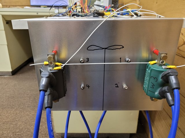
For software development I have everything mocked up in the "office", including a 5 Ohm Coil and a 3 Ohm coil with spark plugs connected.
On a whim I decided to see what happened if I disconnected one of the plug wires at the coil.
I disconnected from the 5 Ohm first and ran the system. The plug that was connected continued to fire but the spark looked a little weaker, orange instead of blue.
Then I disconnected the a plug from the 3 Ohm coil and ran the system. Holly crap!!! It sounded like the cannon on the front of an A10 only angrier!!! My computer screen went black so I couldn't hit the pause button. Next was me dancing around trying to remember which switch to turn off.
Since inquiring minds want to know, I contacted Dynatek tech support.
Long story short, there is only one secondary winding on Dynatek dual plug coils. Both plugs are in series with the secondary winding. This insures that the plugs fire simultaneously. The 3 Ohm coil stored enough energy to cause an internal arc, maybe to the core. In any event, the advice from tech support is "The internal arcing is not healthy for the coil though so should be avoided altogether.".
Why the 5 Ohm coil continued to fire on the connected plug (without the audible arc) is still a mystery.
Wes
I had an interesting experience yesterday.
For software development I have everything mocked up in the "office", including a 5 Ohm Coil and a 3 Ohm coil with spark plugs connected.
On a whim I decided to see what happened if I disconnected one of the plug wires at the coil.
I disconnected from the 5 Ohm first and ran the system. The plug that was connected continued to fire but the spark looked a little weaker, orange instead of blue.
Then I disconnected the a plug from the 3 Ohm coil and ran the system. Holly crap!!! It sounded like the cannon on the front of an A10 only angrier!!! My computer screen went black so I couldn't hit the pause button. Next was me dancing around trying to remember which switch to turn off.
Since inquiring minds want to know, I contacted Dynatek tech support.
Long story short, there is only one secondary winding on Dynatek dual plug coils. Both plugs are in series with the secondary winding. This insures that the plugs fire simultaneously. The 3 Ohm coil stored enough energy to cause an internal arc, maybe to the core. In any event, the advice from tech support is "The internal arcing is not healthy for the coil though so should be avoided altogether.".
Why the 5 Ohm coil continued to fire on the connected plug (without the audible arc) is still a mystery.
Wes
Wes Ragle
Onex #89
Conventional Gear
Long Tips
Hummel 2400 w/Zenith Carb
Prince P Tip 54x50
First Flight 06/23/2020
42.8 Hrs. as of 10/30/21
Onex #89
Conventional Gear
Long Tips
Hummel 2400 w/Zenith Carb
Prince P Tip 54x50
First Flight 06/23/2020
42.8 Hrs. as of 10/30/21
- WesRagle
- Posts: 841
- Joined: Fri Jan 05, 2018 12:35 pm
- Location: Weatherford, Tx
Re: The VeeCU
![]() by BRS » Wed Feb 28, 2024 8:59 pm
by BRS » Wed Feb 28, 2024 8:59 pm
Well that sounds exciting. Too bad you didn't have the whole thing on video. ;-)
-Brock
Sonex-A (s/n 1013)
R2300, P-tip 54/50
Center Stick
V16, TT22
Sonex-A (s/n 1013)
R2300, P-tip 54/50
Center Stick
V16, TT22
-

BRS - Posts: 365
- Joined: Thu Aug 20, 2020 4:50 pm
Re: The VeeCU
![]() by WesRagle » Thu Feb 29, 2024 9:45 am
by WesRagle » Thu Feb 29, 2024 9:45 am
Yep, it would have made it on America's Funniest Home Videos :-)
Wes
Wes
Wes Ragle
Onex #89
Conventional Gear
Long Tips
Hummel 2400 w/Zenith Carb
Prince P Tip 54x50
First Flight 06/23/2020
42.8 Hrs. as of 10/30/21
Onex #89
Conventional Gear
Long Tips
Hummel 2400 w/Zenith Carb
Prince P Tip 54x50
First Flight 06/23/2020
42.8 Hrs. as of 10/30/21
- WesRagle
- Posts: 841
- Joined: Fri Jan 05, 2018 12:35 pm
- Location: Weatherford, Tx
Re: The VeeCU
![]() by WesRagle » Wed Mar 20, 2024 5:05 pm
by WesRagle » Wed Mar 20, 2024 5:05 pm
HI Guys,
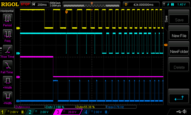
I've been hammering on the VeeCU. Here is a trace of a normal engine start.
Since I don't have hardware yet, the bread board is programmed to accept rising edges of the top trace as the front secondary ignition inputs and the falling edges as rear cylinder secondary ignition input. It's just an easy way to get pulses 180 degrees out of phase with a single input.
So, ...
The yellow trace is/are the secondary ignition inputs which will be robbed from the secondary ignition coils.
The light blue trace is voltage to the secondary ignition coils. It replaces the inputs I stole :-)
The magenta trace is the output enable pin. While low the engine control IC outputs are enabled.
The dark blue trace is the injector pulses going to the right front cylinder.
For safety reasons, I don't allow any ignition or injector pulses until both the front and rear secondary ignition pulses have been seen during the most recent 10 seconds.
So the sequence goes like this:
The first falling edge of the top trace signals that the rear secondary ignition pulse was seen.
Then, when the rising edge is seen, both forward and rear have been seen withing 10 seconds and the outputs are enabled as seen on the magenta trace.
As soon as the outputs are enabled, since this is the first start since power up, a primer pulse is applied to all cylinders. This can be seen by the "wide" first pulse on the dark blue trace. This is a one time thing per power cycle unless the prime is manually rearmed.
On subsequent rising edges you can see the ignition pulses on the light blue trace. The pulses are initially in "impulse mode" behaving much like the secondary always has except the secondary has been retarded to 3 Deg. after TDC, hence like an impulse mag. As the engine passes from "Cranking" to "Starting" the ignition switches to Dwell control and pulls the ignition advance from the "Engine Tune". As the engine passes from "Starting to Running" the Dwell time is further reduced to 12 mSec as per Dyna Tec's advice.
So, it takes a minimum of three blades to fire the engine.
A lot of words for a simple pic :-)
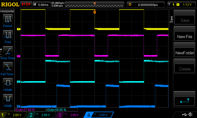
One more scope pic. This pic turns off all but the secondary ignition pulses and the injector pulses. During the early starting phase the pulses are "aimed" at the center of the down stroke. Since this is a "semi-sequential/staged sequential" system every other pulse hits an open intake valve. The other will hit half way down the power stroke. As the engine speeds up the injection pulses are timed to end just before TDC.

I implemented the reversionary mode and it works great on the bench. Right after engine start, a stability check begins. Once the engine is stable, the phase relation of the alternator pulses to the input secondary ignition pulses is calculated. If during engine run the secondary ignition pulses go away (for a heart stopping 1/2 sec), or has 10 percent missing pulses, the alternator takes over to drive ignition and injection. All of this is reported by the only means I currently have, winks and blinks of the panel LED.
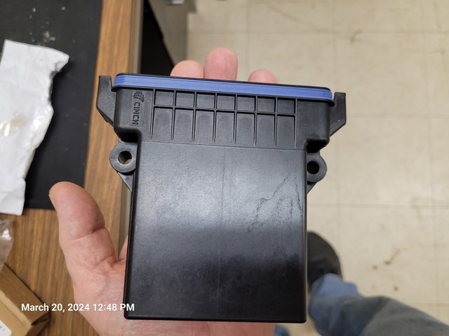
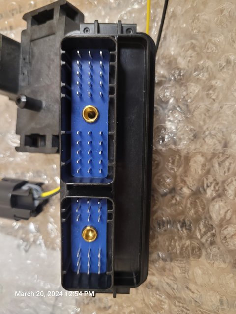
I couldn't resist buying a copy of the enclosure for motivation. I like it. Every VeeCU electronic component is extended temp range. I intend to install the unit forward of the firewall. This enclosure is just about perfect for that purpose.
Just the right size. The right number of pins. Optional ferrites on all pins. Optional vent with "hydrophobic" membrane. Very tight/nice seal. Very affordable with sealed mating connectors.
Anyway, if you can't tell, I'm get'n stoked. The user interface (i.e. switch reads and de-bounce, LED flash patterns etc. ...) is as far as I can go on the bread board. Software is just about ready to hook up to a real engine for "FMEA". It's gonna be fun :-) The schematic is complete and layout is under way.
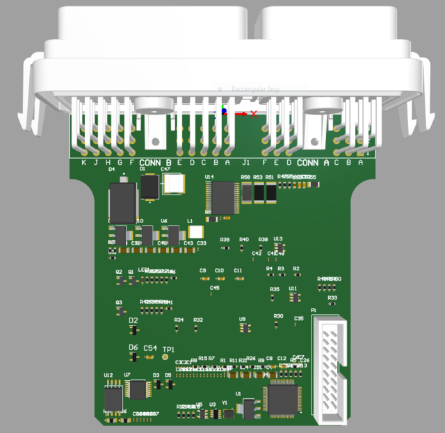
The Design Engineer did this just to get an idea of how crowded, or not, the board will be. Not all components dragged on yet, most notably the IGBTs for ignitiion drive, but it's not going to be bad.
Forever Forward,
Wes
I've been hammering on the VeeCU. Here is a trace of a normal engine start.
Since I don't have hardware yet, the bread board is programmed to accept rising edges of the top trace as the front secondary ignition inputs and the falling edges as rear cylinder secondary ignition input. It's just an easy way to get pulses 180 degrees out of phase with a single input.
So, ...
The yellow trace is/are the secondary ignition inputs which will be robbed from the secondary ignition coils.
The light blue trace is voltage to the secondary ignition coils. It replaces the inputs I stole :-)
The magenta trace is the output enable pin. While low the engine control IC outputs are enabled.
The dark blue trace is the injector pulses going to the right front cylinder.
For safety reasons, I don't allow any ignition or injector pulses until both the front and rear secondary ignition pulses have been seen during the most recent 10 seconds.
So the sequence goes like this:
The first falling edge of the top trace signals that the rear secondary ignition pulse was seen.
Then, when the rising edge is seen, both forward and rear have been seen withing 10 seconds and the outputs are enabled as seen on the magenta trace.
As soon as the outputs are enabled, since this is the first start since power up, a primer pulse is applied to all cylinders. This can be seen by the "wide" first pulse on the dark blue trace. This is a one time thing per power cycle unless the prime is manually rearmed.
On subsequent rising edges you can see the ignition pulses on the light blue trace. The pulses are initially in "impulse mode" behaving much like the secondary always has except the secondary has been retarded to 3 Deg. after TDC, hence like an impulse mag. As the engine passes from "Cranking" to "Starting" the ignition switches to Dwell control and pulls the ignition advance from the "Engine Tune". As the engine passes from "Starting to Running" the Dwell time is further reduced to 12 mSec as per Dyna Tec's advice.
So, it takes a minimum of three blades to fire the engine.
A lot of words for a simple pic :-)
One more scope pic. This pic turns off all but the secondary ignition pulses and the injector pulses. During the early starting phase the pulses are "aimed" at the center of the down stroke. Since this is a "semi-sequential/staged sequential" system every other pulse hits an open intake valve. The other will hit half way down the power stroke. As the engine speeds up the injection pulses are timed to end just before TDC.
I implemented the reversionary mode and it works great on the bench. Right after engine start, a stability check begins. Once the engine is stable, the phase relation of the alternator pulses to the input secondary ignition pulses is calculated. If during engine run the secondary ignition pulses go away (for a heart stopping 1/2 sec), or has 10 percent missing pulses, the alternator takes over to drive ignition and injection. All of this is reported by the only means I currently have, winks and blinks of the panel LED.
I couldn't resist buying a copy of the enclosure for motivation. I like it. Every VeeCU electronic component is extended temp range. I intend to install the unit forward of the firewall. This enclosure is just about perfect for that purpose.
Just the right size. The right number of pins. Optional ferrites on all pins. Optional vent with "hydrophobic" membrane. Very tight/nice seal. Very affordable with sealed mating connectors.
Anyway, if you can't tell, I'm get'n stoked. The user interface (i.e. switch reads and de-bounce, LED flash patterns etc. ...) is as far as I can go on the bread board. Software is just about ready to hook up to a real engine for "FMEA". It's gonna be fun :-) The schematic is complete and layout is under way.
The Design Engineer did this just to get an idea of how crowded, or not, the board will be. Not all components dragged on yet, most notably the IGBTs for ignitiion drive, but it's not going to be bad.
Forever Forward,
Wes
Wes Ragle
Onex #89
Conventional Gear
Long Tips
Hummel 2400 w/Zenith Carb
Prince P Tip 54x50
First Flight 06/23/2020
42.8 Hrs. as of 10/30/21
Onex #89
Conventional Gear
Long Tips
Hummel 2400 w/Zenith Carb
Prince P Tip 54x50
First Flight 06/23/2020
42.8 Hrs. as of 10/30/21
- WesRagle
- Posts: 841
- Joined: Fri Jan 05, 2018 12:35 pm
- Location: Weatherford, Tx
Re: The VeeCU(Plugs & Coils)
![]() by WesRagle » Mon Mar 25, 2024 10:13 pm
by WesRagle » Mon Mar 25, 2024 10:13 pm
HI Guys,
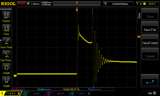
While I'm set up to test coils and plugs I had to go ahead and compare the 3 Ohm Coils and the 5 Ohm coils. The VeeCU monitors the output of the 5V pre-regulator which feeds the 3.3 V regulator which provides CPU power. When the 5V regulator drops out of regulation the system resets. The 5V regulator is low drop out so the VeeCU will reset at about 6 volts. So, I wanted to know if the plugs would still be firing at 6 V, at least in air. I had read where Brock and others were using, or switching to, iridium plugs so I tested those as well to see if I got a little better/longer spark.
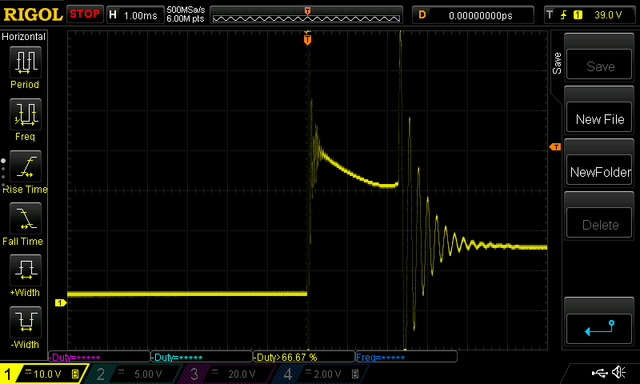
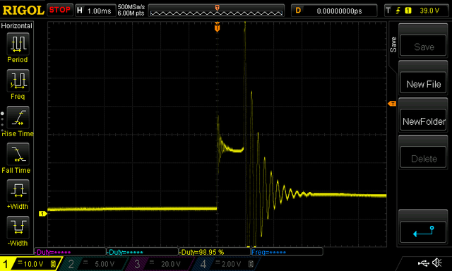
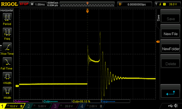
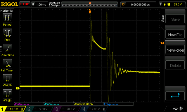
Here are the results (same plug gap):
3 Ohm Coil @ 13V with standard plugs (removed at last annual).
3 Ohm Coil @ 13V with iridium plugs.
3 Ohm Coil @ 6V with standard plugs.
3 Ohm Coil @ 6V with iridium plugs.
=========================================================================
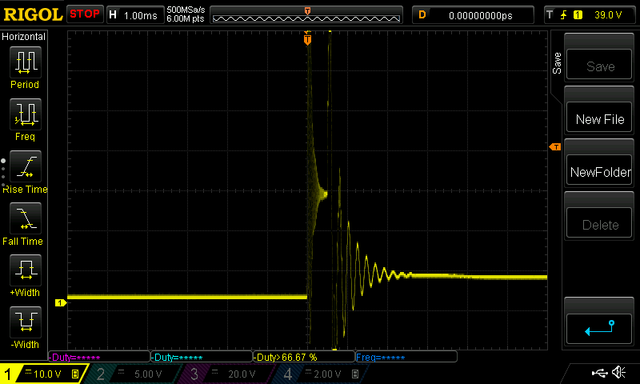
5 Ohm Coil @ 13V with standard plugs.
5 Ohm Coil @ 13V with iridium plugs.
5 Ohm Coil @ 6V with standard plugs.
5 Ohm Coil @ 6V with iridium plugs.
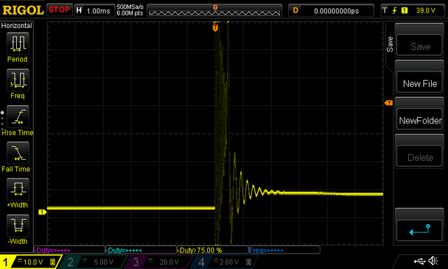
Not a lot of difference in the spark between normal and iridium plugs. Of course the iridium spark didn't dance around in the gap like the normal spark does. Both the "regular" and iridium plugs were miss-firing on the 5 Ohm coil at 6 volts. I just happened to catch a worse spark on the iridium plug.
The 3 Ohm coil was still firing nicely down to 6 volts.
Under normal operating conditions (13 V) the 3 Ohm coil produced a 2.5 mSec spark while the 5 Ohm produced a 1.5 mSec spark. Exactly the ratio you would expect.
BTW, the tests were done with 12 mSec dwell. I took a brief look at the sparks with longer dwell times and it didn't make a noticeable difference.
Anyway, I'm still on the fence on whether to switch to 5 Ohm coils or not.
We'll See,
Wes
While I'm set up to test coils and plugs I had to go ahead and compare the 3 Ohm Coils and the 5 Ohm coils. The VeeCU monitors the output of the 5V pre-regulator which feeds the 3.3 V regulator which provides CPU power. When the 5V regulator drops out of regulation the system resets. The 5V regulator is low drop out so the VeeCU will reset at about 6 volts. So, I wanted to know if the plugs would still be firing at 6 V, at least in air. I had read where Brock and others were using, or switching to, iridium plugs so I tested those as well to see if I got a little better/longer spark.
Here are the results (same plug gap):
3 Ohm Coil @ 13V with standard plugs (removed at last annual).
3 Ohm Coil @ 13V with iridium plugs.
3 Ohm Coil @ 6V with standard plugs.
3 Ohm Coil @ 6V with iridium plugs.
=========================================================================
5 Ohm Coil @ 13V with standard plugs.
5 Ohm Coil @ 13V with iridium plugs.
5 Ohm Coil @ 6V with standard plugs.
5 Ohm Coil @ 6V with iridium plugs.
Not a lot of difference in the spark between normal and iridium plugs. Of course the iridium spark didn't dance around in the gap like the normal spark does. Both the "regular" and iridium plugs were miss-firing on the 5 Ohm coil at 6 volts. I just happened to catch a worse spark on the iridium plug.
The 3 Ohm coil was still firing nicely down to 6 volts.
Under normal operating conditions (13 V) the 3 Ohm coil produced a 2.5 mSec spark while the 5 Ohm produced a 1.5 mSec spark. Exactly the ratio you would expect.
BTW, the tests were done with 12 mSec dwell. I took a brief look at the sparks with longer dwell times and it didn't make a noticeable difference.
Anyway, I'm still on the fence on whether to switch to 5 Ohm coils or not.
We'll See,
Wes
Wes Ragle
Onex #89
Conventional Gear
Long Tips
Hummel 2400 w/Zenith Carb
Prince P Tip 54x50
First Flight 06/23/2020
42.8 Hrs. as of 10/30/21
Onex #89
Conventional Gear
Long Tips
Hummel 2400 w/Zenith Carb
Prince P Tip 54x50
First Flight 06/23/2020
42.8 Hrs. as of 10/30/21
- WesRagle
- Posts: 841
- Joined: Fri Jan 05, 2018 12:35 pm
- Location: Weatherford, Tx
Re: The VeeCU
![]() by WesRagle » Tue Mar 26, 2024 4:50 pm
by WesRagle » Tue Mar 26, 2024 4:50 pm
HI Guys,
I've been re-running some power dissipation numbers and wanted to know what normal power dissipation will be. It dawned on me that I should just measure the current through the coils instead of using calculated numbers.
I was told by Dynatek Tech Support that the max recommended dwell for the 5 Ohm coil is 12 mSec., 10 mSec for the 3 Ohm coils. I'm going to set 12 mSec as the standard Dwell so I can use whatever coil I like.
Here are some measurements taken at 13 V power:
During start each 3 Ohm coil draws just about 3.5 Amps (No dwell control).
@ 15 Hz (900 RPM) each 3 Ohm coil draws 0.4 Amps.
@ 65 Hz (3900 RPM) each 3 Ohm coil draws 1.8 Amps.
With dwell control the current increases linearly with RPM.
If I mentally rewind to when I decided I had to control dwell, it was so I could get the entire EFI system current to below what my present secondary ignition draws at Idle.
With 3 Ohm coils, dwell at 12 mSec., and using a Walbro GSL414 fuel pump, at idle I'm down to:
2 x 0.4 Amps for ignition
3 Amps for the fuel pump.
Less than a 1 Amp for injection.
Way less than 1 amp for the ECU.
-----------------------------------------
Less than 5 amps total for the entire system.
That's less than my present secondary ignition system draws at idle.
So, I'm going to quit worrying about which coils to use and just keep my 3 Ohm coils. Besides, I have a 35 amp alternator to pump the battery back up ;-)
Wes
Wes Ragle
Onex #89
Conventional Gear
Long Tips
Hummel 2400 w/Zenith Carb
Prince P Tip 54x50
First Flight 06/23/2020
42.8 Hrs. as of 10/30/21
Onex #89
Conventional Gear
Long Tips
Hummel 2400 w/Zenith Carb
Prince P Tip 54x50
First Flight 06/23/2020
42.8 Hrs. as of 10/30/21
- WesRagle
- Posts: 841
- Joined: Fri Jan 05, 2018 12:35 pm
- Location: Weatherford, Tx
Who is online
Users browsing this forum: No registered users and 5 guests


