


random user submitted photo
Actual Flying Rotax Installs
Re: Actual Flying Rotax Installs
![]() by GraemeSmith » Thu Jan 21, 2021 7:13 pm
by GraemeSmith » Thu Jan 21, 2021 7:13 pm
SonexN76ET wrote:
What do you guys think?
Jake
Though on an AeroVee - my builder "stiffened" the exposed sagging rubber by applying a hose clamp around it.
My mental note to think of something better has now "been considering" the idea for 180 hours and I can't some up with something better. Come the time - I'll probably wade through the Lord Mount catalog and see if they have something with stiffer material.
Graeme JW Smith
-

GraemeSmith - Posts: 939
- Joined: Sat May 18, 2019 8:58 am
- Location: RI
Re: Actual Flying Rotax Installs
![]() by SonexN76ET » Thu Jan 21, 2021 7:45 pm
by SonexN76ET » Thu Jan 21, 2021 7:45 pm
Hi Graeme,
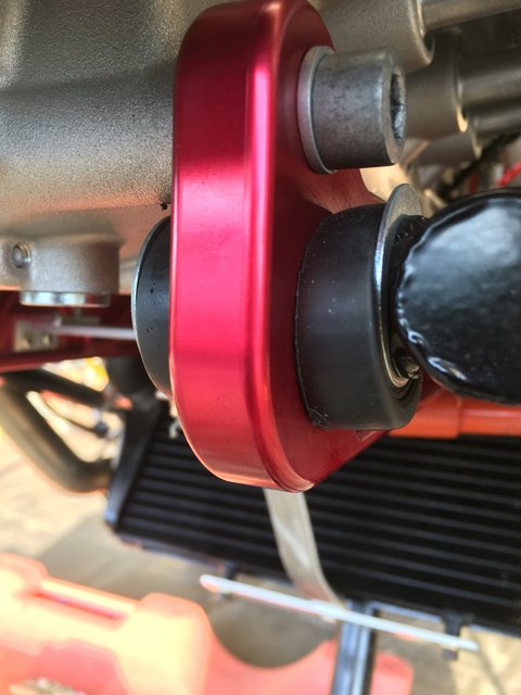
You have some good insight into this and the hose clamps are an interesting idea. The difference in the execution in design between the AeroVee mount and the Rotax mount is the AeroVee has 4130 steel rods that go all the way through the AeroVee accessory plate and when compressed the two rubber bushings on the AeroVee mount and accessory plate likely touch in the middle. On the Rotax mount and mounting bracket there is no 4130 rod on the side of the mount with the two bushings and mounting bracket. It is just a flat surface on the mount where the bushings hit up against the mount. Also on the mounting bar there is a rather large void between the two bushings so it is not just sagging in terms of rubber but to the point where there is now metal to metal contact without the benefit of shock absorption from the bushings when the bushings sag out of the way or tear as in the case described by Herriapower.
Jake
Sonex Tri Gear, Rotax 912 ULS, Sensenich 3 Blade Ground Adjustable Propeller
MGL Velocity EMS, Garmin GTR 200 Comm, GTX 335 ADS B Out Transponder
ILevil AW AHRS & ADS-B In, UAvionix AV20S
200+ hours previously with Aerovee engine
Sarasota, Florida
MGL Velocity EMS, Garmin GTR 200 Comm, GTX 335 ADS B Out Transponder
ILevil AW AHRS & ADS-B In, UAvionix AV20S
200+ hours previously with Aerovee engine
Sarasota, Florida
-

SonexN76ET - Posts: 490
- Joined: Tue Aug 27, 2013 2:39 pm
- Location: Atlanta
Re: Actual Flying Rotax Installs
![]() by Zack » Thu Jan 21, 2021 10:37 pm
by Zack » Thu Jan 21, 2021 10:37 pm
Jake, I agree with all of your points.
I noticed the same thing. I think custom polyurethane bushings would be a good place to start. I did a search and found a few places that will make custom bushings, if there is consensus we can go in together on a small run. I don't have my plane near me, so I'd need someone to provide the dimensions on the attach bar. It has a weird two step inner diameter (ID).
BTW if you have an AN4 (0.250") bolt like I do, and the stock bushing ID is 0.364 (about 3/8") you'll definitely need a sleeve.
SonexN76ET wrote:My observation is that there is a void between the two AeroVee bushings in the mounting bar because the AeroVee bushings are primarily on the outside of the bar and only penetrate it slightly.
I noticed the same thing. I think custom polyurethane bushings would be a good place to start. I did a search and found a few places that will make custom bushings, if there is consensus we can go in together on a small run. I don't have my plane near me, so I'd need someone to provide the dimensions on the attach bar. It has a weird two step inner diameter (ID).
BTW if you have an AN4 (0.250") bolt like I do, and the stock bushing ID is 0.364 (about 3/8") you'll definitely need a sleeve.
- Zack
- Posts: 75
- Joined: Fri Nov 24, 2017 11:45 am
Re: Actual Flying Rotax Installs
![]() by CaseyCooper » Thu Jan 21, 2021 11:48 pm
by CaseyCooper » Thu Jan 21, 2021 11:48 pm
Hey guys,
Just to inform you, I have an5 bolts, not an4’s, in my mount. They are slightly loose in the mount, but sleeves definitely helped. They are 0.030” sleeves which fill out the 0.375” holes in the bushings. But sleeves are definitely necessary to truly tighten and secure the bolts to not shift or wiggle. Mark at Sonex recommended some polyurethane bushings from jegs, but like you found out Jake, polyurethane is super hard. That’s why they use them in suspension (sway bars) applications on cars. Which would not offer much, or any, absorption from the engine to the mount, which could eventually fatigue and crack a mount (in my opinion), as well as just shake the crap out of the plane.
Hose clamps definitely work in some applications, guys with the Jabiru 3300 use that idea, but in this case, you still only have about 3/32” of rubber around the bolts separating the attach bars from the bolts, in a radial load.
Today Mark had contacted me and requested some photos to see exactly what can be done so I took a bunch and sent them his way. I should hear back soon if Mark has any further suggestions.
N7777X
Tailwheel
Rotax 912
3 blade Warp Drive
Tailwheel
Rotax 912
3 blade Warp Drive
- CaseyCooper
- Posts: 50
- Joined: Sat Aug 01, 2020 6:49 pm
- Location: Tucson, Az
Re: Actual Flying Rotax Installs
![]() by SonexN76ET » Fri Jan 22, 2021 12:05 am
by SonexN76ET » Fri Jan 22, 2021 12:05 am
Sonex Tri Gear, Rotax 912 ULS, Sensenich 3 Blade Ground Adjustable Propeller
MGL Velocity EMS, Garmin GTR 200 Comm, GTX 335 ADS B Out Transponder
ILevil AW AHRS & ADS-B In, UAvionix AV20S
200+ hours previously with Aerovee engine
Sarasota, Florida
MGL Velocity EMS, Garmin GTR 200 Comm, GTX 335 ADS B Out Transponder
ILevil AW AHRS & ADS-B In, UAvionix AV20S
200+ hours previously with Aerovee engine
Sarasota, Florida
-
SonexN76ET - Posts: 490
- Joined: Tue Aug 27, 2013 2:39 pm
- Location: Atlanta
Re: Actual Flying Rotax Installs
![]() by SonexN76ET » Fri Jan 22, 2021 12:43 am
by SonexN76ET » Fri Jan 22, 2021 12:43 am
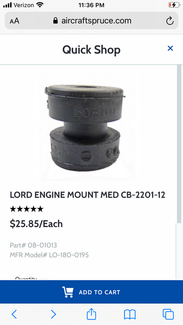
If we machined the through holes on the mounting bars to .8 inches straight through we could potentially use Lord Engine Mount CB-2201. Perhaps we should run this by Sonex as a possible solution?
Specifications can be found here for the Lord engine mounts:
https://www.aircraftspruce.com/catalog/pdf/cb2201tds.pdf
Jake
Sonex Tri Gear, Rotax 912 ULS, Sensenich 3 Blade Ground Adjustable Propeller
MGL Velocity EMS, Garmin GTR 200 Comm, GTX 335 ADS B Out Transponder
ILevil AW AHRS & ADS-B In, UAvionix AV20S
200+ hours previously with Aerovee engine
Sarasota, Florida
MGL Velocity EMS, Garmin GTR 200 Comm, GTX 335 ADS B Out Transponder
ILevil AW AHRS & ADS-B In, UAvionix AV20S
200+ hours previously with Aerovee engine
Sarasota, Florida
-
SonexN76ET - Posts: 490
- Joined: Tue Aug 27, 2013 2:39 pm
- Location: Atlanta
Re: Actual Flying Rotax Installs
![]() by Zack » Fri Jan 22, 2021 2:36 pm
by Zack » Fri Jan 22, 2021 2:36 pm
SonexN76ET wrote:If we machined the through holes on the mounting bars
We would need to re-anodize the attach bars, as the anodized surface is much harder than non-anodized aluminum.
- Zack
- Posts: 75
- Joined: Fri Nov 24, 2017 11:45 am
Re: Actual Flying Rotax Installs
![]() by achesos » Fri Jan 22, 2021 3:08 pm
by achesos » Fri Jan 22, 2021 3:08 pm
Make no mistake - vibration and damping is a complex animal. These are experimental aircraft, but some caution should be applied here when making design changes.
A quick reset perhaps -
What is the problem to be solved here? The appearance of the engine in the mounts in a static configuration?
Maybe more importantly, where does the engine locate itself in flight, while operating, and pulling the plane through the air? This is obviously harder to determine.
Isn't it more important to correctly isolate the engine (while operating) so it can perform primary function (thrust) without destroying itself due to high cycle fatigue (think frequency of vibration amplitude). I seem to remember something about conservation of energy... pretty sure the physics involved here are real.
These isolators are also then protecting (hopefully) the rest of the aircraft and everything attached to it from vibration fatigue as well.
Randomly changing the stiffness of an engine isolator does not negate the energy (excitation forces) created from the engine rotating. That energy is either transmitted or remains self-contained (and absorbed) by the engine assembly.
This is serious R&D stuff. Appropriate caution and data collection is my unsolicited advice.
Sonex N857SX
AeroVee, Taildragger, Dual Stick
AeroVee, Taildragger, Dual Stick
- achesos
- Posts: 33
- Joined: Tue Sep 22, 2015 9:19 pm
- Location: Delavan, Wisconsin
Re: Actual Flying Rotax Installs
![]() by Zack » Fri Jan 22, 2021 6:00 pm
by Zack » Fri Jan 22, 2021 6:00 pm
achesos wrote:What is the problem to be solved here? The appearance of the engine in the mounts in a static configuration?
Achesos, if I understand Herraripower correctly the problem is bushing failure which allows movement of the engine within the mount while it is running. Herraripower, do you have any pictures you can share? I agree that caution is important. Changing the hardness (durometer) of the bushings seems to be a reasonable (and affordable) place to start as it is just one variable and keeps the mount unchanged. Noise, vibration and harshness will increase with the durometer of the bushings. I don't know how to quantify this and what are acceptable limits.
- Zack
- Posts: 75
- Joined: Fri Nov 24, 2017 11:45 am
Re: Actual Flying Rotax Installs
![]() by CaseyCooper » Fri Jan 22, 2021 11:39 pm
by CaseyCooper » Fri Jan 22, 2021 11:39 pm
Sorry guys, I had to render some photos so I could actually post them.
- Attachments
-
- And here you can see the deformation/elongation of the hole, as well as how the second tier of the bushing actually shifted also.
-
- Here’s the bushing deformation.
-
- Here you can see where the attach bar moved to.
-
- Here is the front left. You can see the sleeve/pin I made so I was able to actually torque the bolt down.
-
- Here you can see the front right, it’s slightly sagged. The front left really took most the beating.
N7777X
Tailwheel
Rotax 912
3 blade Warp Drive
Tailwheel
Rotax 912
3 blade Warp Drive
- CaseyCooper
- Posts: 50
- Joined: Sat Aug 01, 2020 6:49 pm
- Location: Tucson, Az
Who is online
Users browsing this forum: No registered users and 8 guests


