


random user submitted photo
FYI
18 posts
• Page 1 of 2 • 1, 2
FYI
![]() by Onex107 » Sun Jun 27, 2021 9:15 pm
by Onex107 » Sun Jun 27, 2021 9:15 pm
I have 335 hours on my Onex 107 and for your information I and my friend in Tenn. are adding NACA vents to both sides of the bottom Cowl. My temps, both cyl and egt are O.K. but I have had three electrical system failures, coils and volt reg.,which I think is due to the heat at the firewall. The Onex has a tight engine compartment and the only air moving through behind the engine is the air through the cylinders. My friend in Tenn. is in the first 100 hours on his engine and has cyl head temps that are high, witch is expected on a new engine. . We both purchased NACA vents from the RV catalog and are installing them on both sides of the lower cowl to bring in outside air and hopefully increase the air flow through the cylinders. If there is no benefit they can be easily closed off.
OneX 107
N2107X
N2107X
- Onex107
- Posts: 494
- Joined: Mon Mar 24, 2014 6:44 pm
- Location: Peoria, IL
Re: FYI
![]() by Scott Todd » Mon Jun 28, 2021 10:08 am
by Scott Todd » Mon Jun 28, 2021 10:08 am
This is interesting. Cooling systems on our engines work because we create a pressure differential forcing air from the top thru the cylinders to the low pressure side, the bottom. The top inlets face forward getting Total pressure. The bottom exit faces perpendicular to the flow which is defined as Static pressure. This difference is technically called Dynamic pressure and it usually creates around 1/4 - 1/3 PSI for us, which is NOT very much.
When someone wants carb air from the lower cowl, we usually recommend they encase the carb inlet to avoid adding pressure to the lower cowl. Certified airplanes often use Scat tubing picked off the top rear baffles to provide additional air for things like oil coolers and other things. We expect more Total air than we need under normal operating conditions so this usually works well if all the other leak paths are sealed. Picking off a minimal amount of this Total pressure air, like certified airplanes, is a better plan than adding any air at all to the lower cowl. We want to keep the pressure difference between the top and bottom as high as possible for best cylinder cooling.
I think a small Scat like tubing directed at the electronics from the rear of the top baffle is a more efficient solution. We are not trying to cool a large source like an oil cooler so it won't take much. I would start with 1/2 inch and add one on one side for the regulator and one on the other for the coils. This gives us direct cooling for what really needs cooled while minimizing the effect on the total cowl pressure differential. Most EFIS's have aux temp inputs we could use to monitor the changes and it would be interesting to see the differences.
- Scott Todd
- Posts: 353
- Joined: Mon Jun 24, 2019 7:40 pm
- Location: Chandler, AZ
Re: FYI
![]() by Bryan Cotton » Mon Jun 28, 2021 5:46 pm
by Bryan Cotton » Mon Jun 28, 2021 5:46 pm
Scott Todd wrote:The bottom exit faces perpendicular to the flow which is defined as Static pressure.
With the ramp in front of the exit, I'd hope it would be lower than static pressure.
Bryan Cotton
Poplar Grove, IL C77
Waiex 191 N191YX
Taildragger, Aerovee, acro ailerons
dual sticks with sport trainer controls
Prebuilt spars and machined angle kit
Year 2 flying and approaching 200 hours December 23
Poplar Grove, IL C77
Waiex 191 N191YX
Taildragger, Aerovee, acro ailerons
dual sticks with sport trainer controls
Prebuilt spars and machined angle kit
Year 2 flying and approaching 200 hours December 23
-

Bryan Cotton - Posts: 5035
- Joined: Mon Jul 01, 2013 9:54 pm
- Location: C77
Re: FYI
![]() by GraemeSmith » Mon Jun 28, 2021 6:00 pm
by GraemeSmith » Mon Jun 28, 2021 6:00 pm
Bryan Cotton wrote:Scott Todd wrote:The bottom exit faces perpendicular to the flow which is defined as Static pressure.
With the ramp in front of the exit, I'd hope it would be lower than static pressure.
The ramp is really there to ensure when you are climbing the air doesn't spill into the negative pressure slot, hit the firewall and pressurize the back of the cowl area. The ramp / lip is there to deflect the air till it has passed onto the belly.
If you make the negative pressure slot bigger in a fore and aft direction - you have to deepen the ramp to prevent the spill into the back of the firewall when you climb. Which creates more drag. Hence high power aircraft use opening cowl flaps or gills that open to temporarily increase the area of the slot (with a corresponding increase in drag) and can be closed when you level off and speed up and get more airflow.
There was a post a couple of weeks ago y someone who was trying an opening cowl flap.
Graeme JW Smith
-

GraemeSmith - Posts: 939
- Joined: Sat May 18, 2019 8:58 am
- Location: RI
Re: FYI
![]() by Scott Todd » Mon Jun 28, 2021 6:17 pm
by Scott Todd » Mon Jun 28, 2021 6:17 pm
It doesn't really get much lower than free stream static. As Graeme points out, the ramp essentially helps to make sure the exit sees perpendicular at various angles. A curved surface can lower the pressure but its pretty hard to emulate. A side problem with a larger ramp is it causes turbulence behind it, which tends to add energy. Its all a trade-off.
The bottom line is cooling is dependent on the pressure difference forcing the air across the cylinders. Adding air into the lower cowl hurts this.
The bottom line is cooling is dependent on the pressure difference forcing the air across the cylinders. Adding air into the lower cowl hurts this.
- Scott Todd
- Posts: 353
- Joined: Mon Jun 24, 2019 7:40 pm
- Location: Chandler, AZ
Re: FYI
![]() by WesRagle » Mon Jun 28, 2021 9:33 pm
by WesRagle » Mon Jun 28, 2021 9:33 pm
Hi Guys,
A single data point. Here is a graph of indicated airspeed vs. impact pressure.
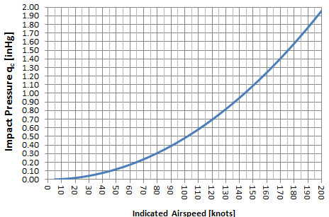
We tend to cruise around at about 100 kts. That gives an impact pressure of about 0.5 in.hg or 6.8 in H2O. I hooked up a manometer and measured the pressure drop across the baffling while cruising at 3000 RPM or approximately 100 kts. It measured 6.5 in H2O. That was with a large aft facing air exit that I hoped would have made for some negative pressure at the outlet. Apparently the exit "scoop" didn't help much.
Ref: https://sonexbuilders.net/viewtopic.php?f=5&t=5226&start=150#p43710.
Wes
A single data point. Here is a graph of indicated airspeed vs. impact pressure.
We tend to cruise around at about 100 kts. That gives an impact pressure of about 0.5 in.hg or 6.8 in H2O. I hooked up a manometer and measured the pressure drop across the baffling while cruising at 3000 RPM or approximately 100 kts. It measured 6.5 in H2O. That was with a large aft facing air exit that I hoped would have made for some negative pressure at the outlet. Apparently the exit "scoop" didn't help much.
Ref: https://sonexbuilders.net/viewtopic.php?f=5&t=5226&start=150#p43710.
Wes
Wes Ragle
Onex #89
Conventional Gear
Long Tips
Hummel 2400 w/Zenith Carb
Prince P Tip 54x50
First Flight 06/23/2020
42.8 Hrs. as of 10/30/21
Onex #89
Conventional Gear
Long Tips
Hummel 2400 w/Zenith Carb
Prince P Tip 54x50
First Flight 06/23/2020
42.8 Hrs. as of 10/30/21
- WesRagle
- Posts: 841
- Joined: Fri Jan 05, 2018 12:35 pm
- Location: Weatherford, Tx
Re: FYI
![]() by racaldwell » Tue Jun 29, 2021 10:00 am
by racaldwell » Tue Jun 29, 2021 10:00 am
The cowl flap should be a consideration. It took me a week's worth of effort which is not a big deal in the grand scheme of things. I could increase or decrease the exit area at will. I currently have this set up with about 60 sq. in. open area fully opening and about 12 sq. in. fully closed. It is the slots for the exhaust pipes that give about 12 sq. in. of open area that I cannot control.
Here is a picture of it finished. You can see the spring in the back on the linkage that holds it open if the cable breaks. The linkage is connected to the lip so it extends and retracts with the flap.
Rick Caldwell
Xenos 0057
Here is a picture of it finished. You can see the spring in the back on the linkage that holds it open if the cable breaks. The linkage is connected to the lip so it extends and retracts with the flap.
Rick Caldwell
Xenos 0057
- Attachments
-
- Cowl Flap Finished Sm.jpg (137.5 KiB) Viewed 3147 times
- racaldwell
- Posts: 399
- Joined: Thu May 22, 2014 4:52 pm
Re: FYI
![]() by Onex107 » Tue Jun 29, 2021 10:32 am
by Onex107 » Tue Jun 29, 2021 10:32 am
I understand the need for negative pressure in the lower cowl and I base my addition of NACA vents on the poor air passages in the Aerovee cylinder heads and the observation of a small amount of oil the exits on top of the cowl, behind the prop, and flows back on top. I suspect, no measurements data, that the top side of the engine is over pressurized and I'm getting a back flow behind the prop. The oil could be coming from the front seal but there is no evidence of a leak. The next flight and the temps. will till the story. The NACA vents are sexy looking, even it they are blocked off.
OneX 107
N2107X
N2107X
- Onex107
- Posts: 494
- Joined: Mon Mar 24, 2014 6:44 pm
- Location: Peoria, IL
Re: FYI
![]() by Onex107 » Mon Jul 05, 2021 5:35 pm
by Onex107 » Mon Jul 05, 2021 5:35 pm
O.K. youz guys. I hear and understand your theory and numbers on engine cooling, but I went ahead and added the NACA vents to my bottom cowl. It took $14 dollars and one hour of work. Not a big investment. the results on the first test flight were dramatic. My temps on the MGL were different. the CHT's were 50 degrees lower and the EGT;s were 100 degrees lower. I attributed that to outside air on the RDAC where the thermocouples are connected. So------next test. I took a piece of alum tape and covered the two rows of connections where the thermocouples and the oil temp and pressure are connected. Very thin, covered them up. A flight this afternoon in 89 degree temp resulted in normal, like I had before, cht and egt temps.
My question now is: If outside air on the thermocouple connections, not on the couples tw feet away, can reduce the temps why doesn't the hot air from the cylinders distort the thermocouple temps before I put the NACA vents in?
Could it be that this cowling is different than others?
Oil cooler on top, no bottom cowl entry.
Let's hear from the experts.
OneX 107
N2107X
N2107X
- Onex107
- Posts: 494
- Joined: Mon Mar 24, 2014 6:44 pm
- Location: Peoria, IL
Re: FYI
![]() by WesRagle » Mon Jul 05, 2021 7:11 pm
by WesRagle » Mon Jul 05, 2021 7:11 pm
Hi Maurice,
I'll give this a shot.
It's likely that the "problem" you are seeing is the results of poor reference junction compensation (cold junction compensation) by the RDAC. If you ask a scientist how a TC works he/she will tell you that the emf generated by a TC is a function of the line integral of the temperature gradient along the length of thermocouple wire. If you ask engineers they will likely tell you the voltage generated is a function of T1 - T2 where T1 is the temperature at the sensing (hot) point and T2 is the temperature where the TC voltage is measured.
All of the equations and tables which are used to correlate the measured voltage with the temperature at the tip of the TC assume a T2 of zero degrees centigrade, which of course is rarely the case. So ..., enter reference junction or CJ compensation. The data acquisition system must measure the temperature where the TC joins copper and use that temperature to adjust the measured voltage before using that voltage to calculate the temperature reading. It sounds like the RDAC is doing a poor job of that.
The point is that, assuming a properly implemented system, you can take a blow torch to a point between the sensing point and the measurement point and it will not effect the T/C reading until the T/C is shorted, burned in two, or the extreme temperature soaks to the TC wire end thus effecting T1 .
However, I don't understand how they were able to adjust/miss the reading by 100 Deg.
Edit:
BTW, you didn't use copper extension wire on your TCs did you?
Wes
Wes Ragle
Onex #89
Conventional Gear
Long Tips
Hummel 2400 w/Zenith Carb
Prince P Tip 54x50
First Flight 06/23/2020
42.8 Hrs. as of 10/30/21
Onex #89
Conventional Gear
Long Tips
Hummel 2400 w/Zenith Carb
Prince P Tip 54x50
First Flight 06/23/2020
42.8 Hrs. as of 10/30/21
- WesRagle
- Posts: 841
- Joined: Fri Jan 05, 2018 12:35 pm
- Location: Weatherford, Tx
18 posts
• Page 1 of 2 • 1, 2
Who is online
Users browsing this forum: No registered users and 26 guests


